Laser beam-combined space debris removal system based on separated multiple-telescope form

A space debris and laser beam combining technology, applied in the space field, can solve problems such as thermal deformation of components, achieve the effect of improving the impact, weakening the thermal deformation of the mirror surface, and avoiding high costs

Active Publication Date: 2014-11-19
CHANGCHUN INST OF OPTICS FINE MECHANICS & PHYSICS CHINESE ACAD OF SCI
View PDF4 Cites 9 Cited by
  • Summary
  • Abstract
  • Description
  • Claims
  • Application Information

AI Technical Summary

Problems solved by technology

[0006] The present invention provides a space debris removal system based on separate multi-telescope laser beam combining in order to solve the p

Method used


Image

  • Laser beam-combined space debris removal system based on separated multiple-telescope form
  • Laser beam-combined space debris removal system based on separated multiple-telescope form
  • Laser beam-combined space debris removal system based on separated multiple-telescope form

Examples


specific Embodiment approach 1

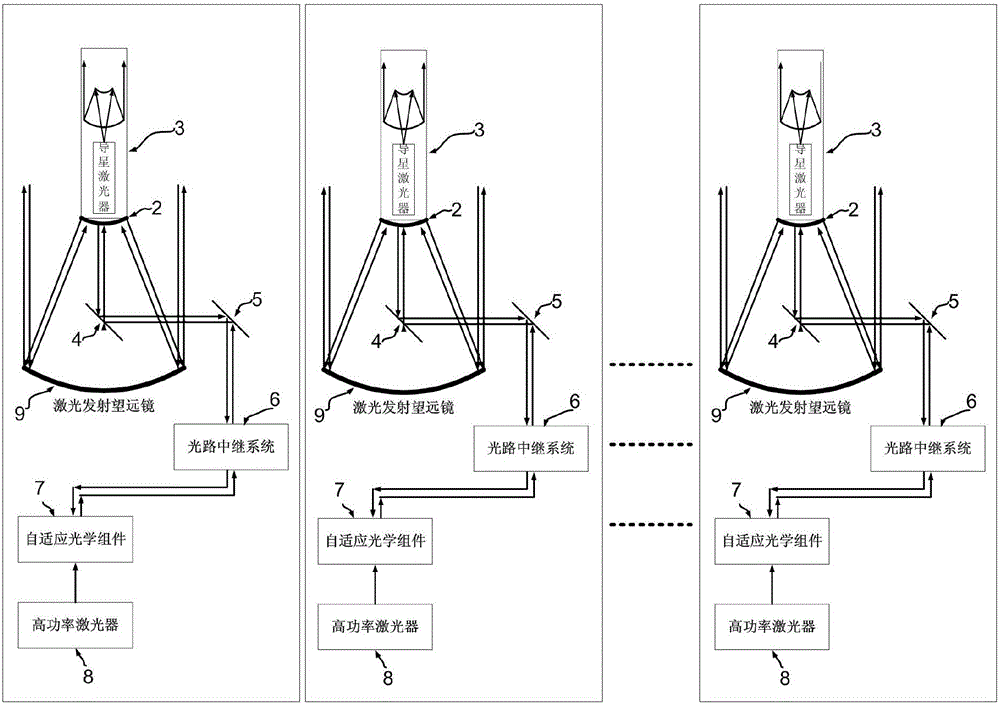
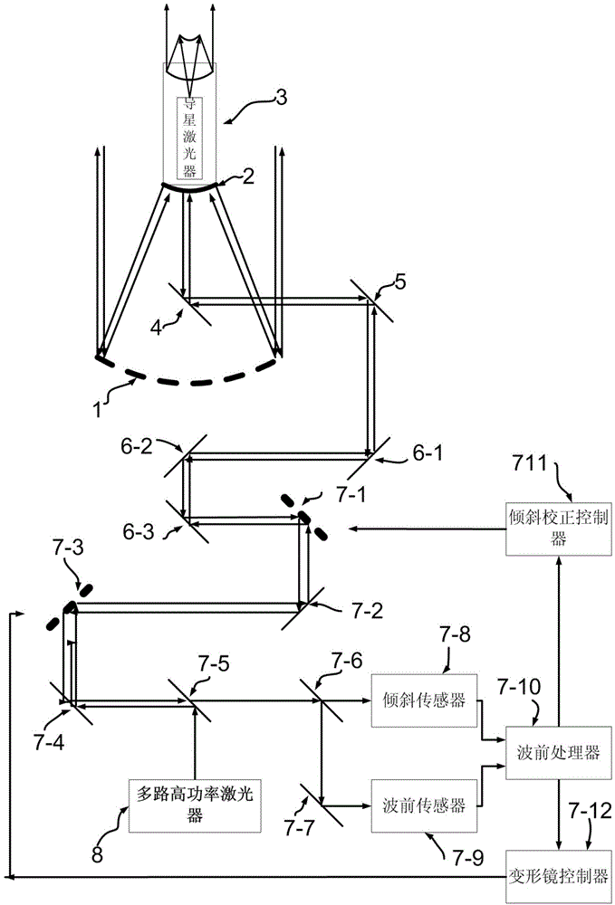
[0015] Specific implementation mode 1. Combination Figure 1 to Figure 5 Describe this embodiment, based on the laser beam combining space debris removal system in the form of separate multi-telescopes, for the form of separate multi-telescopes, each telescope system has a set of corresponding support and target tracking systems. Each telescope system is mainly composed of a laser emitting telescope, a laser guide unit 3, an optical path relay system 6, an adaptive optics component 7 and a high-power laser emitter 8. Wherein the main optical system composed of monolithic primary mirror 1 and secondary mirror 2 is installed on a set of support and target tracking system to form a laser emitting telescope; the laser guide unit 3 is installed on the back of secondary mirror 2 to emit a beam of laser light to At an altitude of about 90 kilometers, a laser guide star is formed, and the telescope receives the light of the guide star. After passing through the optical path relay syst...


PUM


Abstract

The invention discloses a laser beam-combined space debris removal system based on a separated multiple-telescope form, relates to the field of space technology and solves the problem that elements in optical paths are deformed due to heating in the process of space debris removal by the conventional ground high-energy laser emission system. According to the system, multiple beams of high-power lasers are emitted to space debris from the ground, and an ablation effect on the space debris is realized through the superposition of energy of the multiple laser beams. In order to improve the action effect of the laser beams on the space debris, the adaptive optical technology is adopted to correct optical element thermal deformation and disturbance caused by atmosphere in the system; meanwhile, the laser star guiding technology is used in the system, so that the action effect on faint space targets is improved. The space debris removal system is a manner for realizing the removal of space debris on the earth surface; the principle of energy superposition is used in the system, and multiple beams of lasers are used for emission, so that space debris at different orbit altitudes can be processed, the technology realization difficulty of each key unit is reduced, the maintenance is convenient and the cost is reduced correspondingly.

Description

technical field [0001] The invention relates to the field of space technology, in particular to the technology of removing space debris. Background technique [0002] Space debris refers to man-made objects orbiting around the center of the earth, which generally have no use value. It is the product of human space activities, including stopped spacecraft (such as satellites, space stations, space shuttles, etc.), rocket residues used to launch satellites, debris produced by the separation of multi-stage rockets, and collisions between space objects. fragments etc. With the progress of human space activities, the number of space debris presents a growing trend, and its potential collision risk seriously threatens the safe operation of spacecraft in orbit. [0003] Research on space debris focuses on monitoring and removal. To monitor space debris is to give its position and changes in the sky at every moment, and determine its orbit. Although for some regular space debris...

Claims


Application Information

Patent Timeline
IPC IPC(8): G02B23/00G02B17/06G02B27/06
Inventor 王建立林旭东刘欣悦卫沛锋王亮
Owner CHANGCHUN INST OF OPTICS FINE MECHANICS & PHYSICS CHINESE ACAD OF SCI
Why Eureka
Try Eureka