
Method and device for controlling filter boundary frequency band based on genetic algorithm

A genetic algorithm and frequency band control technology, applied in the field of genetic algorithm-based filter boundary frequency band control method and its device, can solve problems such as inability to guarantee optimal data, and achieve the effect of small passband ripple

Inactive Publication Date: 2017-02-22
TIANJIN UNIV
View PDF3 Cites 0 Cited by
  • Summary
  • Abstract
  • Description
  • Claims
  • Application Information

AI Technical Summary

Problems solved by technology

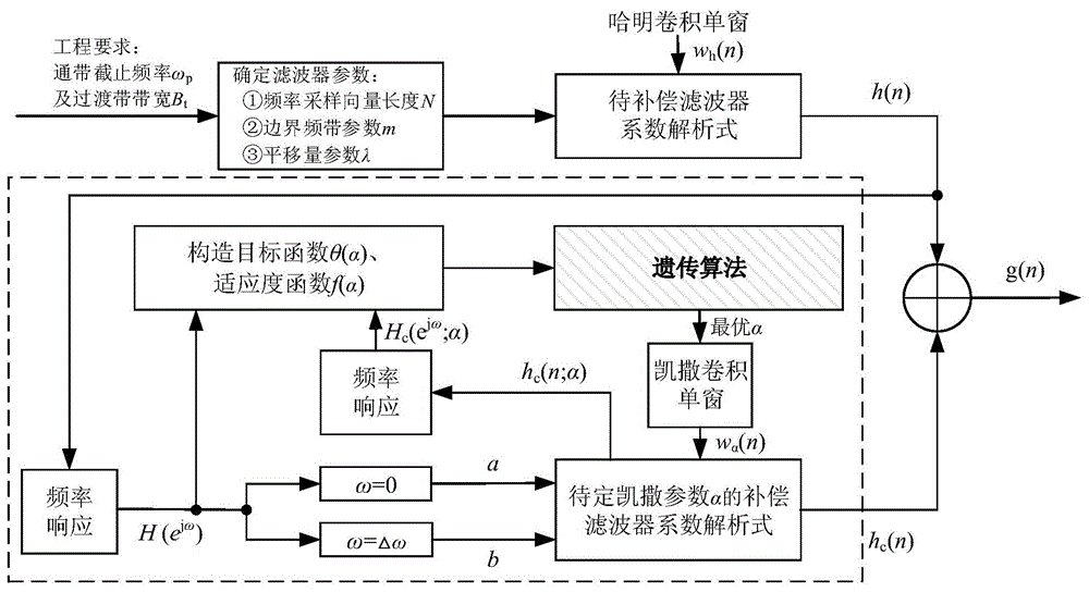
At present, the literature [13] has used the genetic algorithm in the FIR digital filter design - the frequency sampling method to determine the optimal value of the transition zone samples, which solves the problem that the traditional look-up table method cannot guarantee the optimal data
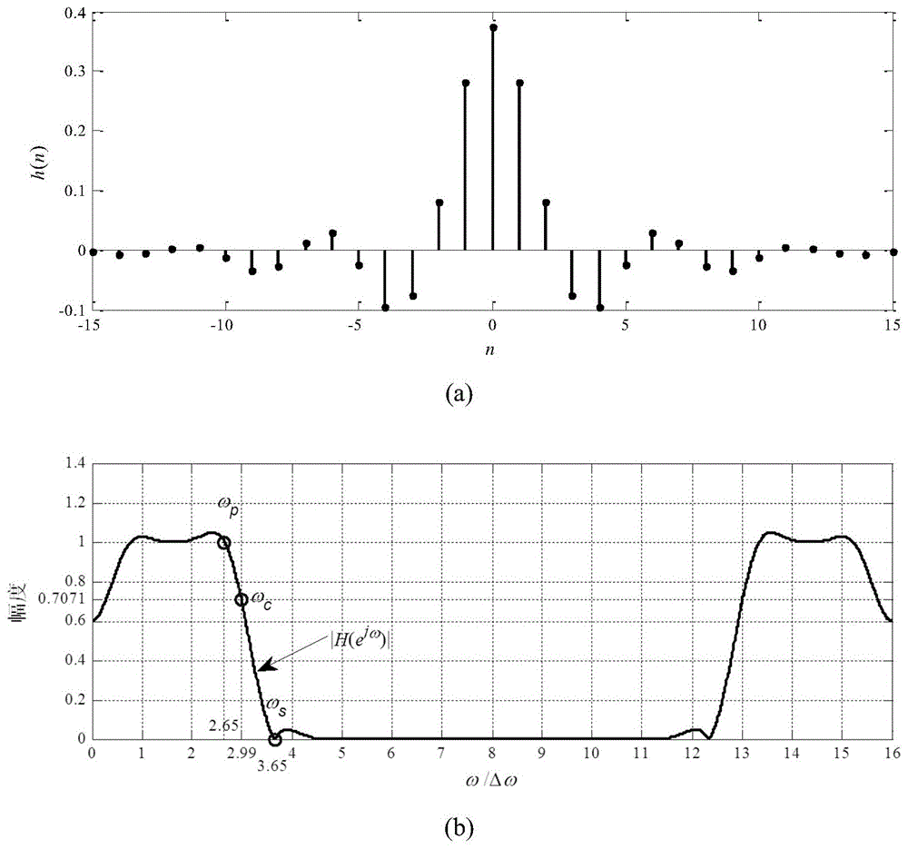
However, the genetic algorithm in [13] can only control the boundary frequency band at the N frequency sampling points of the frequency sampling vector with length N

Method used


Image

  • Method and device for controlling filter boundary frequency band based on genetic algorithm
  • Method and device for controlling filter boundary frequency band based on genetic algorithm
  • Method and device for controlling filter boundary frequency band based on genetic algorithm

Examples


Embodiment Construction

[0046] In order to make the purpose, technical solution and advantages of the present invention clearer, the implementation manners of the present invention will be further described in detail below.

[0047] 101: Design the filter to be compensated;

[0048] (a) the frequency sampling vector setting of the filter to be compensated;

[0049] The present invention introduces an all-phase filter design method for filter design, and the design method needs to set a frequency sampling vector H whose length is N. In order to facilitate the translation of the filter boundary frequency at any point, here H is set as an even symmetrical frequency sampling mode (that is, H(k)=H(N-1-k), k=0,...,N-1 ), as shown in the following formula (1)

[0050]

[0051] In the vector H of formula (1), the number of "1"s on the left and right sides is equal to m, so it is called even symmetrical frequency sampling. Set the frequency sampling interval Δω=2π / N, based on the even symmetric frequenc...


PUM


Abstract

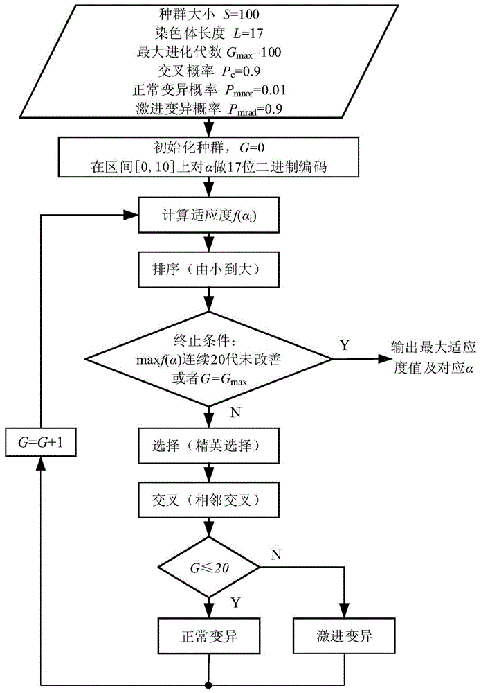
The invention discloses a filter boundary frequency band control method and device based on a genetic algorithm. The method comprises the steps that the filter frequency sampling vector length, boundary frequency band parameters and horizontal moving amount parameters are obtained according to the passband cut-off frequency of a filter and the bandwidth of a transitional band of the filter; the coefficient of a filter to be compensated with the length of 2N-1 is obtained accordingly; the optimist Caesar parameter obtained through operation of the genetic algorithm is substituted into a coefficient analytic expression of a compensation filter to obtain the coefficient of the compensation filter after the optimist Caesar convolution window is optimized; the finally needed filter coefficient is obtained by adding the coefficient of the filter to be compensated to the coefficient of the compensation filter. The device comprises an outer RAM, a DSP and an output driving and displaying circuit. Firstly, the needed passband cut-off frequency of the filter and the bandwidth of the transitional band of the filter are stored into the outer RAM, and then are input into the DSP in real time, and the needed filter coefficient and the transmission curve are obtained finally through processing of internal core algorithms and the like of the DSP and are displayed in real time through the output driver and display circuit.

Description

technical field [0001] The invention relates to the technical field of digital signal processing, in particular to a genetic algorithm-based filter boundary frequency band control method and a device thereof. Background technique [0002] In the design of finite impulse response filter (Finite Impulse Response Filter, FIR filter), it has always been a technology to take into account the good transmission performance of the filter (that is, to ensure that the passband ripple is small enough and the stopband attenuation is large enough) and the filter boundary frequency band is precisely controlled. problem. This problem is prominent in both classical filter design methods and modern filter design methods. [0003] Classical filter design methods, such as the window function method, can set the boundary frequency band parameter ω c Substituting directly into the ideal filter formula to obtain the filter coefficients, but since the ideal filter coefficients are infinitely lon...

Claims


Application Information

Patent Timeline
Patent Type & Authority Patents(China)
IPC IPC(8): G06F19/00
Inventor 黄翔东景森学
Owner TIANJIN UNIV
Learn More