Automatic welding and cooling device and welding method

An automatic welding and cooling device technology, applied in auxiliary devices, welding equipment, auxiliary welding equipment, etc., can solve the problems of inability to weld, difficult to weld thin-walled pipes, etc., to reduce heat input, reduce high temperature residence time, and reduce growing effect

Inactive Publication Date: 2014-11-26
HUNAN NENGCHUANG ENVIRONMENTAL PROTECTION TECH
View PDF9 Cites 8 Cited by
  • Summary
  • Abstract
  • Description
  • Claims
  • Application Information

AI Technical Summary

Problems solved by technology

[0004] The technical scheme adopted by the present invention to solve the technical problem is: it mainly inserts an automatic welding cooling device containing circulating cooling water into the inside of the pipe when welding the pipe, and then performs welding, so that the high temperature generated by welding on the outer wall of the pipe is conducted to the pipe through the pipe wall. The automatic welding cooling device, and then the heat is taken away by the circulating cooling water, so as to achieve the purpose of quickly cooling down the welding place of the pipe while welding, which can ensure that the pipe will not be deformed or melted due to the high temperature of the welding place during welding, which will affect the welding effect , especially to solve the problem that thin-walled pipes are generally difficult to weld or even impossible to weld

Method used


Image

  • Automatic welding and cooling device and welding method
  • Automatic welding and cooling device and welding method

Examples


Embodiment 1

[0018] Embodiment 1. The method of the present invention is mainly to insert an automatic welding cooling device containing circulating cooling water into the inside of the pipe when welding the pipe, so that the high temperature generated by welding on the outer wall of the pipe is conducted to the automatic welding cooling device through the pipe wall, and then The heat is taken away by the circulating cooling water, so as to achieve the purpose of rapidly cooling the pipe welding place while welding, which can ensure that the pipe will not be deformed or melted due to the high temperature of the welding place during welding, which will affect the welding effect. Wall pipes are generally difficult to weld or even impossible to weld. The thin-walled pipes are often melted due to the high temperature during welding because of the thin pipe walls. Not only can they not be welded, but they will also damage the pipes. Many places that can use thin-walled pipes can only use thicker...

Embodiment 2

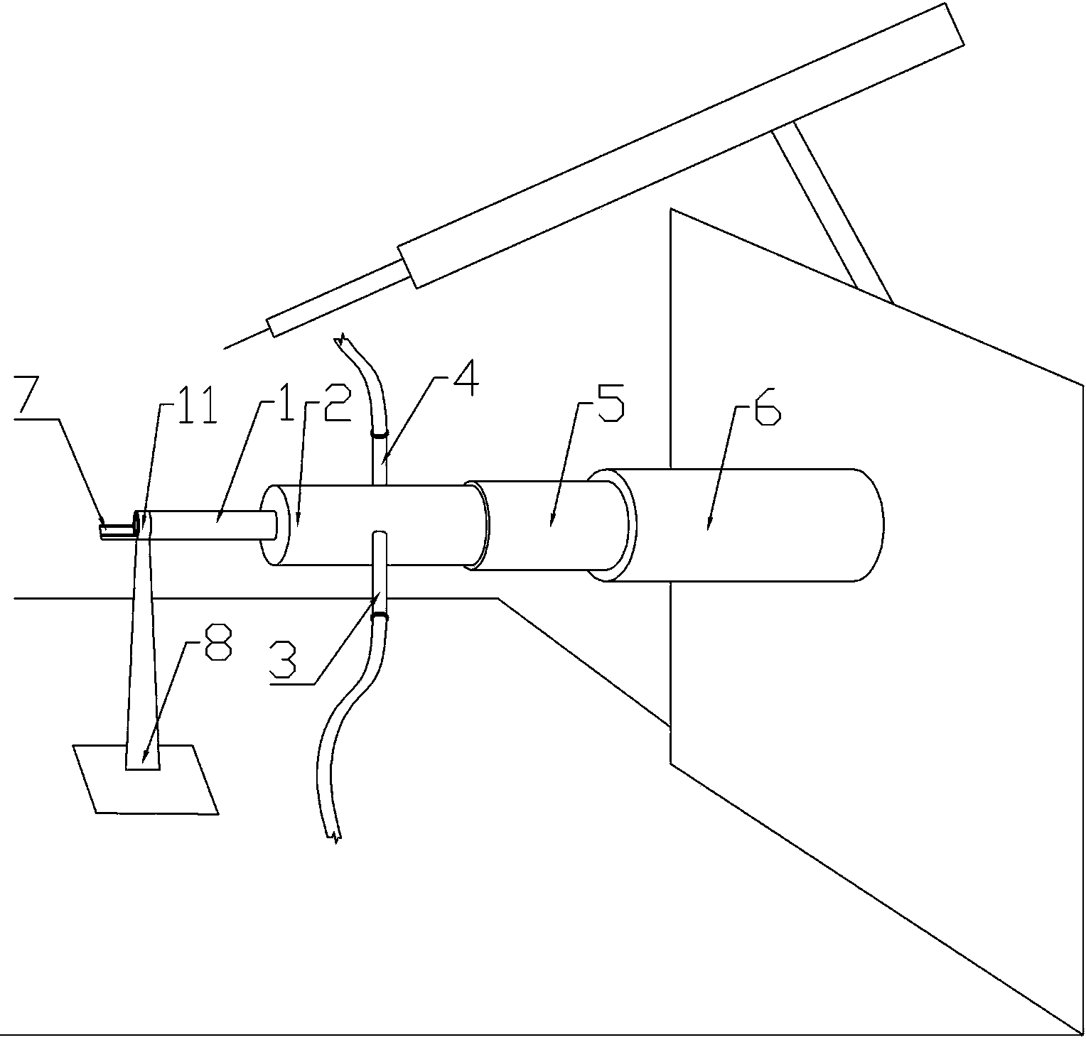
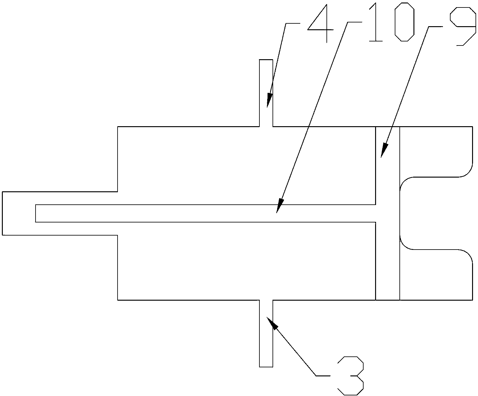
[0019] Embodiment 2, the present invention comprises cylinder liner 6, telescopic cylinder 5 is characterized in that: one end of telescopic cylinder 5 is arranged in cylinder liner 6, the other end of telescopic cylinder 5 is provided with cooling chamber 2, and the other end of cooling chamber 2 is provided with cooling chamber. Both sides of the pipe 1 and the cooling chamber 2 are provided with a water outlet 3 and a water inlet 4, and the front end of the cooling pipe 1 is provided with a balance bracket 8. During welding, the telescopic cylinder 5 and the cooling chamber 2 are extended forward to push the cooling pipe 1 into the target In the pipe, the heat in the welding area is transferred to the cooling pipe 1 through the pipe, and then transferred to the cooling water in the cooling pipe 1 by the cooling pipe 1 to achieve the purpose of controlling the temperature of the welding area. During the welding process, the water inlet and outlet 4 continuously input cooling w...

Embodiment 3

[0020] Embodiment 3, the outer diameter of the telescopic cylinder 5 according to the present invention is slightly smaller than the inner diameter of the cylinder liner 6, so that the telescopic cylinder 5 can be installed in the cylinder liner 6. refer to Figure 1 to Figure 2 , and the rest are the same as the above-mentioned embodiment.


PUM


Abstract

The invention relates to an automatic welding and cooling device and welding method, and belongs to a welding device and a welding method. The technical problems that when pipes are welded, heat radiation performance is poor, and thin and small pipes cannot be welded are mainly solved. According to the technical scheme, the device and method are characterized in that a telescopic air cylinder (5) is arranged in an air cylinder sleeve (6), a cooling chamber (2) is arranged at one end of the telescopic air cylinder (5), a cooling pipe (1) is arranged at the other end of the cooling chamber (2), a water outlet (3) is connected into one side of the cooling chamber (2), and a water inlet (4) is connected into the other side of the cooling chamber (2). The device and method are mainly used for welding and cooling the small pipes or the thin-wall pipes.

Description

technical field [0001] The invention relates to a cooling device and a welding method, in particular to an automatic welding cooling device and a welding method. Background technique [0002] At present, metal pipe to pipe butt welding is an indispensable content in pipe manufacturing and technical application. However, the welding heat process will promote the grain growth in the welding heat-affected zone, resulting in the degradation of the performance of the welded joint, and the welded pipe is easy to weld through and deform. To this end, through certain cooling means, reduce the heat input of the welding heat process to the weld area, control the welding heat cycle in the welding heat affected zone, reduce the width of the welding heat affected zone as much as possible, and reduce the high temperature residence time. Reducing the growth of fine grains is one of the core technologies to effectively guarantee and improve the microstructure and performance of pipe-to-pip...

Claims


Application Information

Patent Timeline
Patent Type & Authority Applications(China)
IPC IPC(8): B23K37/00
CPCB23K37/003
Inventor 周伟波
Owner HUNAN NENGCHUANG ENVIRONMENTAL PROTECTION TECH
Why Eureka
Try Eureka