Apparatus and method for measuring acoustical absorption coefficient by using pulse sound source and sound pressure-particle velocity (PU) probe

A sound absorption coefficient and sound source technology, which is applied in the processing of detection response signals, and the use of sound waves/ultrasonic waves/infrasonic waves to analyze solids, etc., can solve the problems of limited effective frequency response range of speakers, unguaranteed, large error of sound absorption coefficient, etc. Achieve the effect of convenient measurement and adjustment, and expand the measurement frequency range

Inactive Publication Date: 2014-11-26
CHINA FIRST AUTOMOBILE
View PDF4 Cites 2 Cited by
  • Summary
  • Abstract
  • Description
  • Claims
  • Application Information

AI Technical Summary

Problems solved by technology

In addition, due to the limited effective frequency response range of the speaker, it cannot be guaranteed that the signal received by the probe is sufficiently larger than the background noise at low frequencies
Therefore, the current sound pressure-particle velocity probe to measure the sound absorption coefficient of materials has an effective measurement frequency of 300 Hz to 10 kHz. In fact, the error of the sound absorption coefficient measured below 500 Hz is relatively large.

Method used


Image

  • Apparatus and method for measuring acoustical absorption coefficient by using pulse sound source and sound pressure-particle velocity (PU) probe
  • Apparatus and method for measuring acoustical absorption coefficient by using pulse sound source and sound pressure-particle velocity (PU) probe
  • Apparatus and method for measuring acoustical absorption coefficient by using pulse sound source and sound pressure-particle velocity (PU) probe

Examples


Embodiment 1

[0055] The acoustic material measured in the case is melamine foam, and the length, width, and thickness are 1500 mm×670 mm×100 mm, respectively. LMS Q-sources mid-frequency volume sound source is used as the speaker sound source, and the effective frequency range of the sound source is 200 Hz~8 kHz. A B&K 3560C was used as a signal generator and data acquisition system, emitting pink noise with a frequency bandwidth of 6.4 kHz. A balloon was used as the pulse sound source, and Matlab was used for data post-processing.

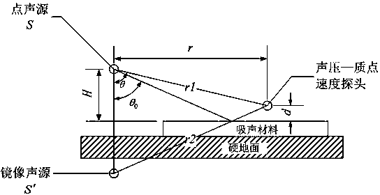
[0056] Such as figure 2 As shown, the material to be tested is laid flat on the ground, the sound pressure-particle velocity probe is located at the geometric center of the material, and the height of the probe from the surface of the material is d =1 cm. Place the sound source directly above the sound pressure-particle velocity probe, that is , the height of the sound source from the surface of the material H =100 cm. Excite the sound source of the l...


PUM


Abstract

The invention provides an apparatus for measuring an acoustical absorption coefficient by using a pulse sound source and a PU probe. The apparatus is characterized in that the PU probe and the pulse sound source are installed on a bracket with adjustable length, the telescopic bracket is provided with a guide groove, a telescopic rod is inserted in the guide groove of the telescopic bracket, a handle is fixedly connected with the back of the telescopic bracket, the telescopic rod can extend out from the left end of the telescopic bracket, the left end of the telescopic bracket is provided with a locking knob which limits the telescopic rod, the head of the right end of the telescopic bracket is a sound source slot, the end head of the telescopic rod is provided with a probe mounting groove, the PU probe is fixedly connected with the probe mounting groove, and the pulse sound source is fixedly connected with the sound source slot. According to the invention, the PU probe and the pulse sound source arranged on the bracket with adjustable length are used for measuring the sound absorption coefficient of a material, the range of measuring frequency of the sound absorption coefficient is expanded, and absorption coefficients in the frequency range of 63 Hz to 20 kHz can be measured; the apparatus can be hand-held, which facilitates measurement and adjustment; the apparatus has no strict requirements on the shapes and thickness of parts, can be used for measurement in various environments and realizes measurement of absorption coefficients of materials in most cases.

Description

technical field [0001] The invention relates to a device and method for measuring sound absorption coefficient by using a pulse sound source and a sound pressure-particle velocity (PU) probe, belonging to the field of sound absorption coefficient measurement of materials. Background technique [0002] Using the sound pressure-particle velocity probe to directly measure the sound pressure and particle vibration velocity near the material, and then obtain the acoustic impedance rate. Under the assumption that the surface of the material reflects plane waves, the acoustic reflection coefficient of the material can be calculated by using the image source model, and finally Get the sound absorption coefficient. Compared with the reverberation chamber method and the impedance tube method, the method of measuring the sound absorption coefficient of the material using the sound pressure-particle velocity probe has no special requirements on the shape and area of ​​the measured mater...

Claims


Application Information

Patent Timeline
Patent Type & Authority Applications(China)
IPC IPC(8): G01N29/04G01N29/44
Inventor 李凌志张智刘英杰
Owner CHINA FIRST AUTOMOBILE
Why Eureka
Try Eureka