Supercharge Your Innovation With Domain-Expert AI Agents!

Resistivity Tomography Detector and System Between Horizontal Boreholes

A technology of horizontal drilling and tomography, used in radio wave measurement systems, electrical/magnetic exploration, measurement of resistance/reactance/impedance, etc. The hole wall is in good contact, and the cable is not easy to be inserted into the hole, etc.

Active Publication Date: 2016-08-31
SHANDONG UNIV
View PDF5 Cites 0 Cited by
  • Summary
  • Abstract
  • Description
  • Claims
  • Application Information

AI Technical Summary

Problems solved by technology

[0005] There are two main problems in the current detection device: firstly, the method of putting the detection cable and electrodes into the horizontal hole mainly depends on using a rod to poke the cables and electrodes into the hole, which makes it difficult for the cables to be inserted into the holes; It is not possible to ensure that the electrodes are equidistant or placed in the specified position; secondly, under dry hole conditions, the electrodes on the detection cable cannot be guaranteed to make good contact with the hole wall

Method used


Image

  • Resistivity Tomography Detector and System Between Horizontal Boreholes
  • Resistivity Tomography Detector and System Between Horizontal Boreholes
  • Resistivity Tomography Detector and System Between Horizontal Boreholes

Examples


Embodiment 1

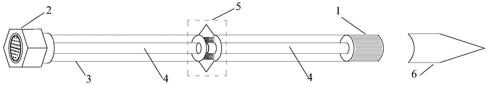
[0047] Example 1: figure 1 It is a structural diagram of a resistivity tomography detector between horizontal boreholes, which mainly consists of a multi-pinhole positive interface 1, a multi-pinhole negative interface 2, an outer casing 3, a multi-core detection cable 4, a hole wall contact device 5 and a sealing Triangular pyramid 6 constitutes. The device as a whole is a linear steel structure, and the interior is completely sealed, solid and firm, ensuring its practical applicability.

[0048] The outer sleeve 3 is a linear internal sealed steel rod-shaped structure, and its two ends are respectively provided with a multi-pinhole positive interface 1 and a multi-pinhole negative interface 2 that can be mated and inserted. The two ends of the steel pipe have multi-pinhole positive and negative interfaces mainly for the interconnection of multiple detectors, which are suitable for detection under different hole depth conditions.

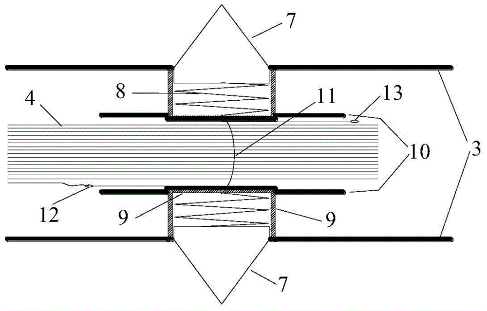
[0049]The sealing triangular cone 6 is ins...

Embodiment 2

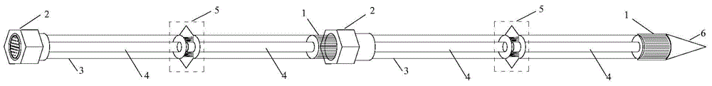
[0058] Embodiment 2: as image 3 , 4 As shown, at least two of the detectors are plugged in series end to end in sequence, a sealed triangular cone 6 is installed on the front end of the most front detector, and the rear end of the end detector connects the multi-core detection cable in the detector through the lead cable 16. 4 connected to the host 17.

Embodiment 3

[0059] Embodiment 3: During actual detection,

[0060] 1) Calculate the number of detectors required according to the depth of the borehole 14;

[0061] 2) Connect multiple detectors in order, and connect the sealing triangle cone 6 to the front end of the inlet, see image 3 ;

[0062] 3) Slowly send the connected detectors 15 into the borehole 14. Of course, each detector can be sent into the borehole 14 one by one according to the environmental conditions on site;

[0063] 4) Connect the connected detector 15 to the host 17 through the lead cable 16, see Figure 4 ;

[0064] 5) Repeat the above 4 steps, put the detector into another hole, and make sure the lead cable connects the detector to the host.

[0065] 6) Supply power to the two contact probes in one hole through the host, at this time, a current field is formed around the two contact probes, and then measure the distance between the two contact probes in the other hole Voltage value;

[0066] 7) The combinati...


PUM


Abstract

The invention discloses a resistivity tomography detector and system between horizontal boreholes, which can detect in dry holes or water holes. The invention is mainly composed of multi-pinhole positive and negative interfaces, steel pipes, multi-core detection cables, hole wall contact devices and sealing triangular cones. The hole wall contact device is composed of a contact probe cone, a spring, an inner sleeve, an insulating sealing plate, a connecting ring and a terminal. The multi-core detection cable is sealed inside the steel pipe, and each core is connected to a hole wall contact device. When detecting, according to the detection depth, use multiple devices to assemble in order, and connect the sealing triangle cone at the inlet end, insert them into the horizontal holes one by one, and connect with the host through the lead wire, so that the dry hole or water hole can be realized. Pore ​​resistivity tomography detection. After detection, disassemble and put away in sequence. The detection device is easy to operate, dual-purpose for water holes and dry holes, and has strong practicability.

Description

technical field [0001] The invention relates to a geophysical detection technology, in particular to a resistivity tomography detector and system between horizontal boreholes in an underground space working face. Background technique [0002] Since the beginning of the 21st century, domestic infrastructure construction is in the ascendant, and before the construction of each infrastructure, whether it is an underground building or an above-ground building, it is necessary to understand the pros and cons of the geological environment in which it is located, so that later design, construction, monitor. Especially for underground engineering construction, during the excavation process, it is necessary to check the geological conditions of the surrounding rock irregularly, because unforeseen geological disasters, such as water gushing, mud gushing, landslides, etc., may occur during the excavation process . If this work cannot be done well, the construction machinery will be d...

Claims


Application Information

Patent Timeline
Patent Type & Authority Patents(China)
IPC IPC(8): G01V3/02G01R27/08
Inventor 苏茂鑫李术才薛翊国高瑜邱道宏林春金
Owner SHANDONG UNIV
Features
  • R&D
  • Intellectual Property
  • Life Sciences
  • Materials
  • Tech Scout
  • Unparalleled Data Quality
  • Higher Quality Content
  • 60% Fewer Hallucinations
Learn More