
Linear high voltage direct current stabilized power supply with IGBT as pass transistor

A high-voltage DC, regulated power supply technology, applied in the direction of converting AC power input to DC power output, electrical components, output power conversion devices, etc., can solve the problem of uncontrolled falling amplitude, poor load capacity, slow response, etc. question

Inactive Publication Date: 2014-11-26
西安派瑞功率半导体变流技术股份有限公司
View PDF7 Cites 6 Cited by
  • Summary
  • Abstract
  • Description
  • Claims
  • Application Information

AI Technical Summary

Problems solved by technology

[0002] At present, the following methods are generally used for the generation of high-voltage direct current: 1) The method of boosting the voltage of the high-voltage transformer is adopted. This method needs to adjust the primary voltage of the high-voltage transformer through a voltage regulator, and then boost the voltage through the transformer, and then obtain high-voltage DC after rectification and filtering. This method needs to control the DC high voltage output by controlling the AC voltage, so the linear control accuracy is poor and the response is slow
2) A voltage doubler rectifier circuit is used. On the one hand, the voltage adjustment of this circuit also needs to be adjusted by a voltage regulator. On the other hand, although the voltage of the voltage doubler rectifier circuit can rise very high, the load capacity is very poor. Once the load is large The voltage drops quickly, and the amplitude of the drop is uncontrolled
3) The switch-type high-voltage DC power supply is boosted by a high-frequency transformer through a high-frequency switching inverter circuit, and then rectified and filtered on the high-voltage side to obtain a high-voltage DC power supply. High-frequency noise is generated on the DC power supply, which will seriously affect the accuracy of the test system and is not conducive to the withstand voltage test of high-voltage semiconductor devices

Method used


Image

  • Linear high voltage direct current stabilized power supply with IGBT as pass transistor
  • Linear high voltage direct current stabilized power supply with IGBT as pass transistor

Examples


Embodiment Construction

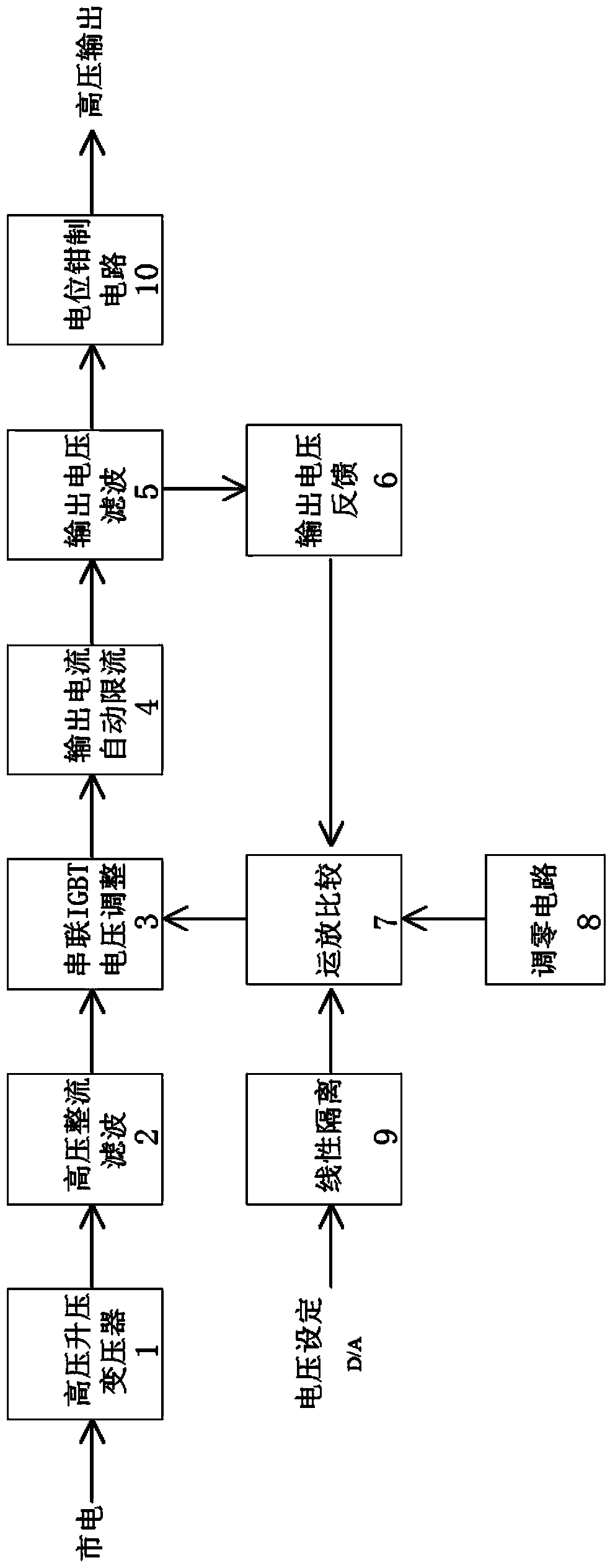
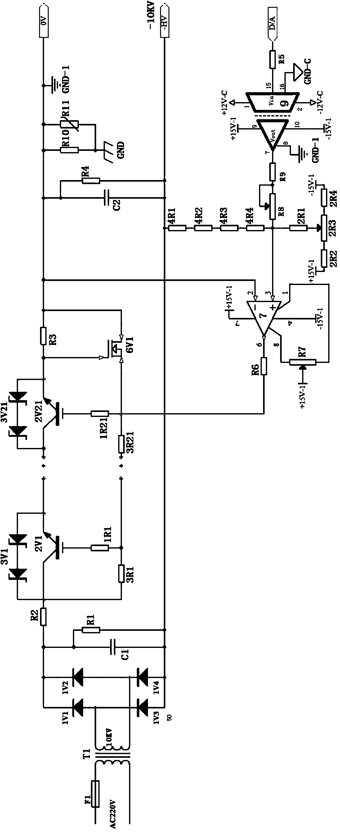
[0016] According to attached figure 1 and attached figure 2 The working principle of the present invention is specified as follows:

[0017] A linear high-voltage DC stabilized power supply using IGBT as a regulator tube, including a high-voltage step-up transformer 1, a high-voltage rectification filter circuit 2, a series IGBT voltage adjustment circuit 3, an automatic current limiting circuit 4, an output voltage filter circuit 5, and an output voltage feedback circuit 6 , operational amplifier comparison circuit 7, zero adjustment circuit 8, setting signal linear isolation circuit 9 and potential clamping circuit 10. A high-voltage step-up transformer 1, a high-voltage rectification filter circuit 2, a series IGBT voltage adjustment circuit 3, an automatic current limiting circuit 4, an output voltage filter circuit 5 and a potential clamping circuit 10 are sequentially connected to form a main circuit. The output voltage feedback circuit 6, the operational amplifier co...


PUM


Abstract

The invention relates to a linear high voltage direct current stabilized power supply with an IGBT as a pass transistor. The power supply is composed of a high voltage boosting transformer, a high voltage rectification filter circuit, a series-connection IGBT voltage regulating circuit, an automatic current limiting circuit, an output voltage filter circuit, a potential holding circuit, an output voltage feedback circuit, an operational amplifier comparator circuit, a zero setting circuit and a set signal linear isolating circuit, wherein the high voltage boosting transformer, the high voltage rectification filter circuit, the series-connection IGBT voltage regulating circuit, the automatic current limiting circuit, the output voltage filter circuit and the potential holding circuit are sequentially connected to form a main circuit, and the output voltage feedback circuit, the operational amplifier comparator circuit, the zero setting circuit and the set signal linear isolating circuit form a control circuit. The linear high voltage direct current stabilized power supply is used for high voltage IGBT device VCES tests, working voltage can reach 10 kV, voltage output can be linearly set and controlled through a computer, voltage output is stable and free of high frequency noise, and direct current square waves with the adjustable width can be obtained through control as needed.

Description

technical field [0001] The invention relates to a linear high-voltage DC stabilized power supply using IGBT as a regulating tube. It is currently used in high-voltage IGBT static parameter test projects, and can also be used in other fields that require linear control to automatically generate high-precision and wide-range high-voltage DC voltage sources. Background technique [0002] At present, the following methods are generally used for the generation of high-voltage direct current: 1) The method of boosting the voltage of the high-voltage transformer is adopted. This method needs to adjust the primary voltage of the high-voltage transformer through a voltage regulator, and then boost the voltage through the transformer, and then obtain high-voltage DC after rectification and filtering. This method needs to control the DC high voltage output by controlling the AC voltage, so the linear control accuracy is poor and the response is slow. 2) A voltage doubler rectifier circ...

Claims


Application Information

Patent Timeline
IPC IPC(8): H02M7/217
Inventor 李更生杨莉于庆
Owner 西安派瑞功率半导体变流技术股份有限公司
Learn More