Rail-spraying magnetic drill floor

A technology of magnetic drilling and rail spraying, which is applied to workbenches, dust removal, chemical instruments and methods, etc., can solve problems such as dust pollution, poor processing environment, and potential safety hazards, improve safety and sanitation, and solve safety problems , the effect of reducing dust pollution

Inactive Publication Date: 2014-12-03
CHENGDU DUJIA ELECTRICAL
View PDF0 Cites 4 Cited by
  • Summary
  • Abstract
  • Description
  • Claims
  • Application Information

AI Technical Summary

Problems solved by technology

[0003] During the design process of the drill floor, how to strengthen the industrial parts or rotate them at multiple angles is considered for easy processing, but when the industrial parts are processed, a lot of industrial waste is generated. Of course, this situation is inevitable. People in the industry There is not much attention to this, but on the one hand, the waste chips will affect the safety of workers during the operation because of the splashing during the production process, and there are safety hazards; on the other hand, the existence of waste chips will make the processing environment worse and cause dust pollution. , so the treatment of waste has become important

Method used


Image

  • Rail-spraying magnetic drill floor

Examples


Embodiment 1

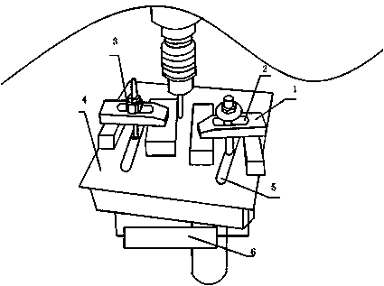
[0020] see figure 1 , The spray rail magnetic drilling platform includes a pressing block 1, a fixing bolt 3, a supporting platform 4, a U-shaped chute 5 and an electromagnet 6. The above-mentioned supporting platform 4 is provided with a U-shaped chute 5 on the horizontal plane, and the pressing block 1 is perpendicular to the horizontal plane. The axis of the axis passes through the U-shaped chute 5, and the above-mentioned fixing bolt 3 passes through the pressing block 1 and extends into the U-shaped chute 5. The pressing block 1 can be moved and adjusted along the U-shaped chute 5 according to the position requirements of the drilling of industrial components. At the processing position, the above-mentioned electromagnet 6 is set under the support platform 4. The electromagnet 6 is set to absorb the waste chips left by the drill bit processing, so that the waste chips will not splash around and affect the worker's operation. It is set under the support platform. It is to...

Embodiment 2

[0023] Similar to Embodiment 1, the spray rail magnetic drill floor includes a pressure block 1, a fixing bolt 3, a support platform 4, a U-shaped chute 5 and an electromagnet 6. The difference is that the above-mentioned support platform 4 is rectangular, and a U-shaped The chute 5, the U-shaped chute 5 is parallel to one side of the support table 4. The axis of the pressing block 1 perpendicular to the horizontal plane passes through the U-shaped chute 5, and the above-mentioned fixing bolt 3 passes through the U-shaped groove 2 of the pressing block 1 and extends into the U-shaped chute 5. The pressing block 1 can be used according to industrial parts The location of the drill hole needs to move along the U-shaped chute 5 to adjust the processing position of the parts. The above-mentioned electromagnet 6 is arranged under the support table 4. The electromagnet 6 is arranged to absorb the waste chips left by the drilling process, so Waste chips will not splash around and aff...

Embodiment 3

[0025] Similar to Embodiment 1 and Embodiment 2, the difference is that the above-mentioned electromagnet 6 is a suction cup type electromagnet, a suspension type electromagnet or a frame type electromagnet, and the magnetic size of the above-mentioned electromagnet 6 is ≧80N / cm 2 . The sucker type electromagnet, suspension type electromagnet or frame type electromagnet is convenient to be placed under the support table 4 .

[0026] The adsorption capacity of the electromagnet 6 should not be too large, so as to prevent affecting the normal operation of other workpieces, it can absorb waste chips and prevent them from splashing, and a certain amount of waste chips can be collected for centralized treatment.


PUM


Abstract

The invention discloses a rail-spraying magnetic drill floor which comprises pressing blocks, fixing bolts, a supporting table, U-shaped sliding chutes and an electromagnet, wherein the U-shaped sliding chutes are formed in the supporting table; the pressing blocks penetrate through the U-shaped sliding chutes in a manner of being perpendicular to the axial line of the horizontal plane; the fixing bolts penetrate through the pressing blocks and perpendicularly extend into the U-shaped sliding chutes; the electromagnet is arranged below the supporting table. According to the rail-spraying magnetic drill floor, the electromagnet is arranged at the bottom of the supporting table, is used for adsorbing sputtering sweeps and can gather the sweeps together for treatment; the safety problem of a worker is solved; the dust pollution is reduced; therefore the worker is safer in an operating process; the safety and sanitation degree of the environment are improved; the rail-spraying magnetic drill floor meets humanistic and enterprise cultures.

Description

technical field [0001] The invention relates to a drill floor, in particular to a rail-jet magnetic drill floor. Background technique [0002] Modern industrial parts mostly use drill floors as operating platforms, and various drill floors have emerged as the times require, and are used in various fields, such as oil drill floors, magnetic drill floors, and so on. [0003] During the design process of the drill floor, how to strengthen the industrial parts or rotate them at multiple angles is considered for easy processing, but when the industrial parts are processed, a lot of industrial waste is generated. Of course, this situation is inevitable. People in the industry There is not much attention to this, but on the one hand, the waste chips will affect the safety of workers during the operation because of the splashing during the production process, and there are safety hazards; on the other hand, the existence of waste chips will make the processing environment worse and ...

Claims


Application Information

Patent Timeline
Patent Type & Authority Applications(China)
IPC IPC(8): B25H1/08B08B15/04
Inventor 罗宾
Owner CHENGDU DUJIA ELECTRICAL
Why Eureka
Try Eureka