Low-abrasion hydraulic machine

A hydraulic machinery, low-wear technology, applied in mechanical equipment, liquid fuel engines, rotary piston machinery, etc., can solve the problems of easy wear and failure of the inner surface of the stator, affecting product performance and life, and improve reliability and life. The effect of improving product performance

Active Publication Date: 2014-12-03
胡阳
View PDF13 Cites 1 Cited by
  • Summary
  • Abstract
  • Description
  • Claims
  • Application Information

AI Technical Summary

Problems solved by technology

[0007] The purpose of the present invention is to solve the problem that the inner surface of the stator is easy to wear and fail due to the sliding friction between the blade and the inner surface of the stator in the existing blade machinery, which af

Method used


Image

  • Low-abrasion hydraulic machine
  • Low-abrasion hydraulic machine
  • Low-abrasion hydraulic machine

Examples


Embodiment 1

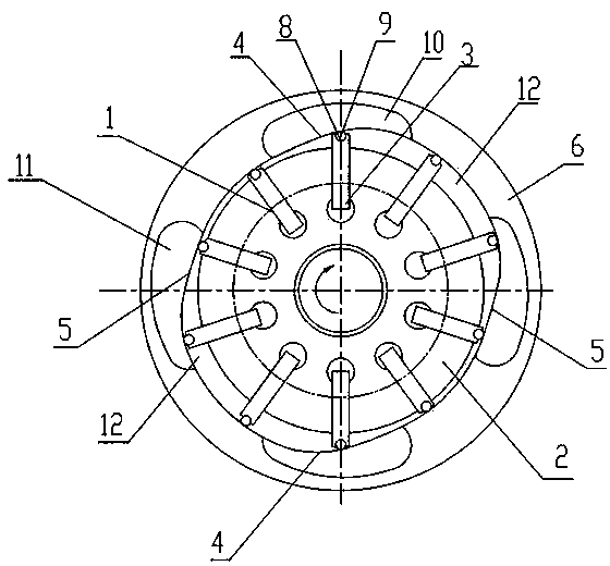
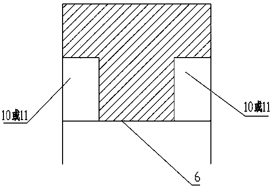
[0035] exist figure 1 In the shown embodiment, a low-wear hydraulic machine comprising a rotor 2 having several radial slots 1, several vanes 3 slidingly arranged in each radial slot 1, arranged outside the rotor 2 and having an inner surface along the circumferential direction A stator 6 with at least one ascending section 4 and at least one descending section 5, side plates 7 arranged at both ends of the stator 6 and the rotor 2, a raceway 8 is provided on the end surface where the outer end of the blade 3 is in contact with the inner surface of the stator 6 , the rolling body 9 is movable in the raceway 8, there is a fluid lubricating film between the rolling body 9 and the raceway 8, the rolling body surface protrudes from the front end of the blade, when the blade slides out, the rolling body surface is in rolling friction contact with the inner surface of the stator, and the stator The ascending section 4 of the inner surface is provided with an inflow window 10, the des...

Embodiment 2

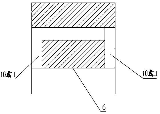
[0039] exist Figure 4 In the shown embodiment, a low-wear hydraulic machine comprising a rotor 2 having several radial slots 1, several vanes 3 slidingly arranged in each radial slot 1, arranged outside the rotor 2 and having an inner surface along the circumferential direction A stator 6 with at least one ascending section 4 and at least one descending section 5, side plates 7 arranged at both ends of the stator 6 and the rotor 2, a raceway 8 is provided on the end surface where the outer end of the blade 3 is in contact with the inner surface of the stator 6 , the rolling body 9 is movable in the raceway 8, there is a fluid lubricating film between the rolling body 9 and the raceway 8, the rolling body surface protrudes from the front end of the blade, when the blade slides out, the rolling body surface is in rolling friction contact with the inner surface of the stator, and the stator The ascending section 4 of the inner surface is provided with an inflow window 10, the de...

Embodiment 3

[0043] exist Figure 5 In the shown embodiment, its technical scheme is basically the same as that of Embodiment 1, the difference is that: the inlet window 10 or the outlet window 11 are provided with three independent ones, and this embodiment is suitable for lower pressure fluid windows. hydraulic machinery.


PUM


Abstract

The invention discloses a low-abrasion hydraulic machine. The low-abrasion hydraulic machine comprises a rotor having multiple radial grooves, a plurality of blades, a stator, and side plates arranged at the two ends of the stator and the rotor, wherein rolling ways are formed in the end surfaces, towards the inner surface of the stator, of the outer ends of the blades; rolling bodies are movably arranged in the rolling ways; fluid lubricating films are arranged between the rolling bodies and the rolling ways; the surfaces of the rolling bodies are projected on the front end surfaces of the blades; when the blades slide to extend out, the surfaces of the rolling bodies and the inner surface of the stator are contacted in a rolling friction manner; flow inlet windows are formed in corresponding positions of an ascending section of the inner surface of the stator or the end surfaces of the side plates; flow outlet windows are formed in corresponding positions of a descending section of the inner surface of the stator or the end surfaces of the side plates; the outer circular surface of the rotor, the inner surface of the stator, adjacent blades and rolling bodies and the side plates form fluid working cavities; the fluid working cavities in the ascending section are communicated with the flow inlet windows; and the fluid working cavities in the descending section are communicated with the flow outlet windows. The low-abrasion hydraulic machine adopts the low-abrasion rolling friction, so that the product performance is improved, the product reliability is improved, and the service life is prolonged.

Description

technical field [0001] The invention relates to the technical field of vane hydraulic machines such as hydraulic vane pumps and motors, in particular to low-wear hydraulic machines. Background technique [0002] The existing hydraulic vane pumps and motors have sliding friction between the vanes and the stator, and the inner surface of the stator is prone to wear and failure, thereby affecting product performance and life. Of course, there are also hydraulic pumps in the prior art that use rolling blades to reduce the problem of easy wear and failure on the inner surface of the stator. [0003] Chinese patent literature (announcement date: September 4, 2002, announcement number: CN 1367319A) discloses a rolling vane hydraulic pump, which relates to the category of positive displacement hydraulic pumps in hydraulic equipment. The hydraulic pump mainly includes a rotor, a blade, a stator, a pump body, and a distribution valve core. The main feature of the invention is that t...

Claims


Application Information

Patent Timeline
IPC IPC(8): F04C2/344F04C15/06F03C2/30
Inventor 胡凯杨天珍
Owner 胡阳
Why Eureka
Try Eureka