Automatic Transmission

A technology of automatic transmission and transmission, which is applied in the direction of vehicle gearboxes, transmission components, transmission devices, etc., can solve problems such as complex structures, and achieve the effects of improving transmission efficiency, simple shift logic, and reducing idling losses

Active Publication Date: 2016-06-08
SHENGRUI TRANSMISSION
View PDF11 Cites 0 Cited by
  • Summary
  • Abstract
  • Description
  • Claims
  • Application Information

AI Technical Summary

Problems solved by technology

Most of the early automatic transmissions (AT) used a multi-stage planetary gear set structure, either with fewer gears or with an overly complex structure.

Method used


Image

  • Automatic Transmission
  • Automatic Transmission
  • Automatic Transmission

Examples


no. 1 example

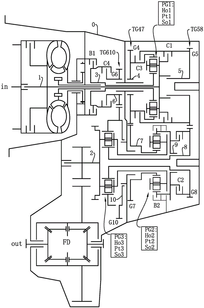
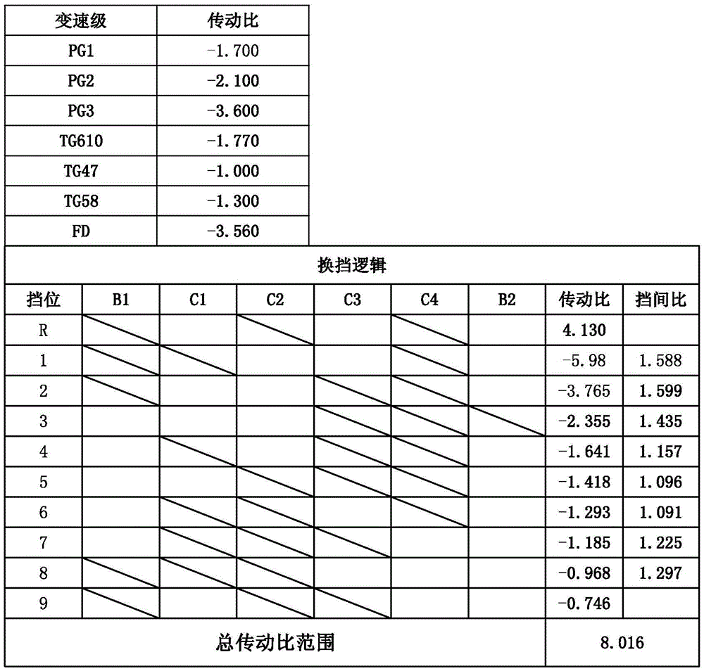
[0035] Such as figure 1As shown, an automatic transmission can realize at least nine forward gears and at least one reverse gear. The input shaft in of the transmission is connected with the first shaft 1 through the starting unit for power input, and the output shaft out of the transmission is connected with the second shaft 2 through the differential FD for power output. The starting unit may be a starting clutch or a hydraulic torque converter or the like.

[0036] The transmission includes two shaft systems, three spur gear sets, three planetary gear sets and six shift units arranged side by side in a common transmission case O. In this technical field, shafts having the same axis and components arranged on these shafts form a shaft system.

[0037] The first shaft system is located on the transmission side, including the first shaft 1, the third shaft 3, the fourth shaft 4, the fifth shaft 5 and the sixth shaft 6, and the second shaft system is located on the driven sid...

no. 2 example

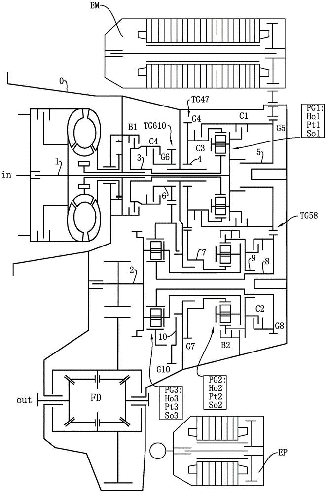
[0064] image 3 Shown is another form of application of the invention, referred to as a hybrid power transmission solution. For simplicity and understanding, only the differences from the first embodiment will be described below.

[0065] The electric motor EM is connected to the fifth shaft 5 through an additional spur gear set, in this case the electric motor EM is arranged parallel to both shaft systems.

[0066] The first shaft 1 extends along the axis of the entire first shaft system, and its two ends are supported on the transmission case 0 . In this case, both ends of the first shaft 1 can be connected to an engine or an electric machine EM. This technical solution enables the transmission of the present invention to have a large number of different application designs. Such a structure is also applicable to the first embodiment.

[0067] The second shaft 2 extends along the axis of the entire second shaft system, and its two ends are supported on the transmission c...


PUM


Abstract

The invention discloses an automatic transmission, which comprises a first shaft system on the transmission side and a second shaft system on the driven side arranged side by side in the same transmission case, and three spur gear sets, three planetary gear sets, four There are two clutches and two brakes, and the two shaftings are connected by multiple power paths to which the three spur gear sets belong. At least nine forward gears and at least one reverse gear are realized with only six shifting units, and the gear ratios of commonly used gears are between 1.091 and 1.297, and the total transmission ratio range reaches 8.016. The gear shifting is smooth and the structure is maintained. It is compact, improves the driving dynamic performance of the vehicle and further reduces fuel consumption, is economical to use, and is conducive to protecting the environment. The automatic transmission is suitable for hybrid drive and has functions suitable for automatic engine start and stop.

Description

technical field [0001] The invention relates to an automatic transmission, in particular to an automatic transmission suitable for use as a main transmission device in a power transmission system of a passenger car. Background technique [0002] In the field of passenger vehicles, automatic transmission (AT) is still the mainstream transmission structure. Most of the early automatic transmissions (AT) used a multi-stage planetary gear set structure, either with few gears or an overly complex structure. Later, the structure of the automatic transmission in which the combination of two shaft systems, spur gear sets and planetary gear sets began to appear. Chinese invention patent CN101275630B has just described such a multi-stage transmission with power shifting. [0003] According to the patent, the transmission includes two shaft systems, three spur gear sets, three planetary gear sets and a plurality of shift units arranged side by side in a common transmission case, wher...

Claims


Application Information

Patent Timeline
Patent Type & Authority Patents(China)
IPC IPC(8): F16H3/66F16H3/72
CPCF16H3/66F16H2200/0065F16H2200/201F16H2200/2046
Inventor 皮特·谭伯格王书翰于新涛李娟娟魏文书刘祥伍
Owner SHENGRUI TRANSMISSION
Why Eureka
Try Eureka