Structured light method for small-angle measurement

A structured light, small-angle technology, applied in measurement devices, optical devices, instruments, etc., to achieve high sensitivity, low cost, and the effect of suppressing influence

Active Publication Date: 2014-12-03
INST OF OPTICS & ELECTRONICS - CHINESE ACAD OF SCI
View PDF5 Cites 6 Cited by
  • Summary
  • Abstract
  • Description
  • Claims
  • Application Information

AI Technical Summary

Problems solved by technology

However, there have been no reports on the use of structured light methods to achieve small-angle measurements.

Method used


Image

  • Structured light method for small-angle measurement
  • Structured light method for small-angle measurement
  • Structured light method for small-angle measurement

Examples


Embodiment Construction

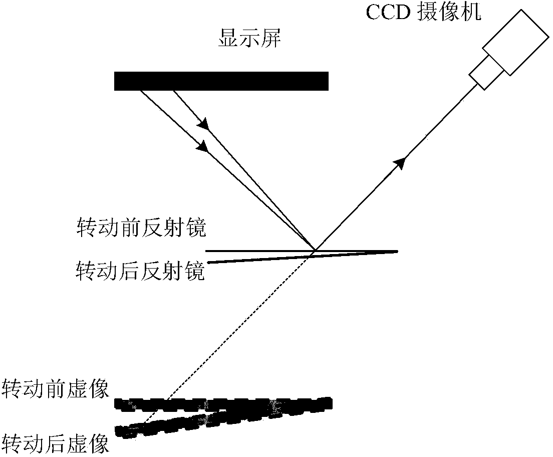
[0018] Such as figure 1 As shown, this system mainly includes CCD camera, display screen and computer. The characteristic pattern generated by the computer is displayed on the display screen, which is photographed and recorded by the CCD camera after being reflected by the measured object or a mirror fixed on the object. That is, CCD shooting and recording the virtual image of the display screen formed by the mirror. When the mirror rotates, the virtual image taken by the camera also rotates. Analyze the virtual image before and after the rotation, and calculate the rotation angle. According to the law of light reflection, half of this angle is the angle at which the mirror rotates. The following takes the display of a two-dimensional sine fringe characteristic pattern on the display screen as an example for description. When other characteristic patterns are displayed, there is a similar measurement process. This example does not include all the contents of this patent.

[00...


PUM


Abstract

Disclosed is a structured light method for small-angle measurement. A measuring system comprises a CCD camera, a display screen and a computer. A feature pattern is displayed on the display screen and projected onto a measured object or a reflector fixed on the object, and the pattern is reflected and then shot by the camera. The reflected feature pattern is shot by the CCD camera, and in other words, a virtual image formed through the reflector on the display screen is shot by the CCD camera. When the object rotates, the virtual image shot by the camera rotates too. The rotating angle of the virtual image can be calculated by analyzing the virtual image before and after rotation. According to the light reflection law, the rotating angle of the object is half of the rotating angle of the virtual image. The measuring system is simple in structure, convenient to use, high in sensitivity, free of special requirements for the environment, and capable of conducting detection in a workshop.

Description

Technical field [0001] The invention relates to an optical angle measurement technology, in particular to a structured light test method for small angle measurement. technical background [0002] Angle measurement is an important part of geometric measurement technology, especially the measurement of small angles has extremely important significance and effect in many fields such as precision machining, aerospace, military and communications. The earliest research on angle measurement technology is mechanical and electromagnetic angle measurement technology, such as multi-tooth indexing table and circular magnetic grid. The main disadvantages of these methods are mostly manual measurement, which is not easy to achieve automation and the measurement accuracy is limited. The optical angle measurement method has attracted people's attention due to its non-contact, high accuracy and high sensitivity. In particular, the development of stable laser light sources has made industrial fie...

Claims


Application Information

Patent Timeline
Patent Type & Authority Applications(China)
IPC IPC(8): G01B11/26
Inventor 赵文川李璐璐范斌
Owner INST OF OPTICS & ELECTRONICS - CHINESE ACAD OF SCI
Why Eureka
Try Eureka