
Method for manufacturing electrochromic element

A component manufacturing, electrochromic technology, applied in nonlinear optics, instruments, optics, etc., can solve the problems of inability to isolate infrared rays and harmful light wave frequencies, high driving voltage, poor color contrast, etc., and achieve the isolation of infrared rays and harmful light wave frequencies. , long-term color change memory effect, low driving voltage effect

Inactive Publication Date: 2014-12-03
TINTABLE SMART MATERIAL CO LTD
View PDF4 Cites 16 Cited by
  • Summary
  • Abstract
  • Description
  • Claims
  • Application Information

AI Technical Summary

Problems solved by technology

[0003] When the above-mentioned known electrochromic unit is applied with a driving voltage, it will produce a color change, and the color change is different depending on the driving voltage, but the driving voltage required by the known electrochromic unit is relatively high, and the color that can be presented Less steps, poorer color pairing, and when the electrochromic unit is known to be powered off, it can maintain color for a short time
Moreover, it is generally known that the electrochromic unit is a liquid crystal element, which requires a high driving voltage, and cannot maintain the color state when the power is turned off, and has a high transmittance to the infrared heat source radiation section, and cannot isolate infrared rays. and harmful light frequency

Method used


Image

  • Method for manufacturing electrochromic element
  • Method for manufacturing electrochromic element
  • Method for manufacturing electrochromic element

Examples


Embodiment Construction

[0036] In order to make the above-mentioned purposes, features and advantages of the present invention more understandable, the preferred embodiments of the present invention will be specifically cited below, together with the accompanying drawings, to be described in detail as follows, wherein:

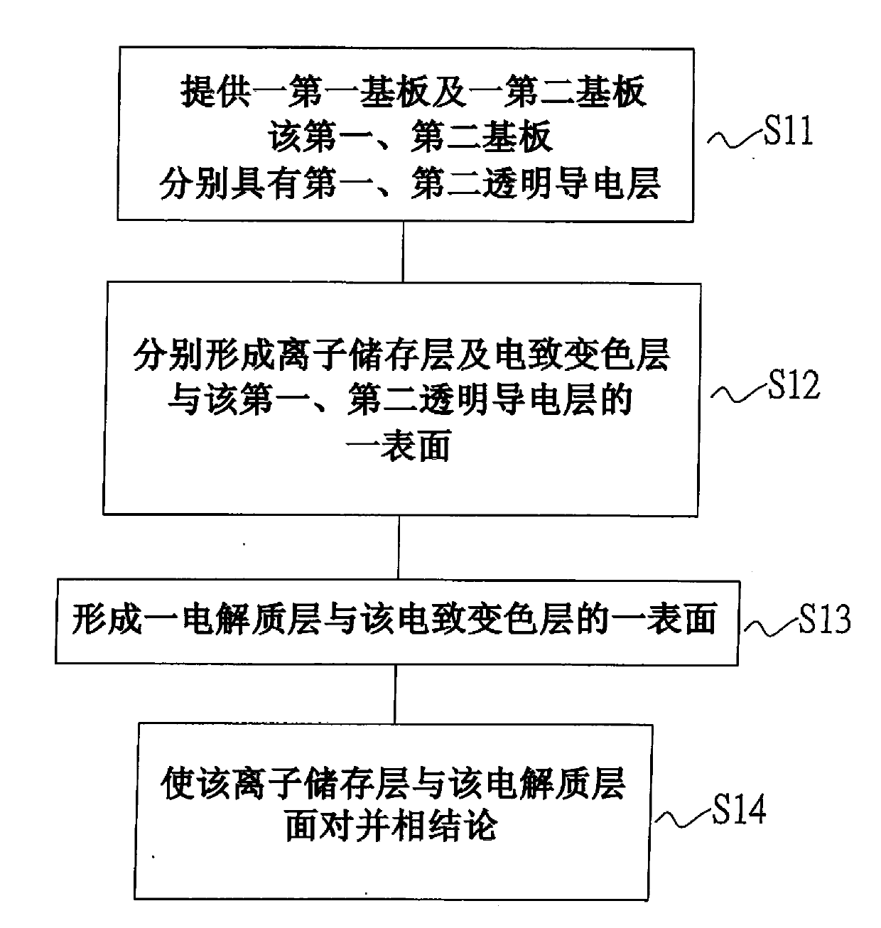
[0037] figure 1 It is a flowchart of a method for manufacturing an electrochromic element according to a preferred embodiment of the present invention; and

[0038] Figure 2 to Figure 6 It is a schematic diagram of the manufacturing method of the electrochromic element in a preferred embodiment of the present invention.

[0039] Please refer to figure 1 and figure 2 , first proceed to step S11, providing a first substrate (12) and a second substrate (14), the first substrate (12) including a first base material layer (121) and a first transparent conductive layer (122) , the second substrate (14) includes a second base material layer (141) and a second transparent conductive la...


PUM


Abstract

The invention relates to a method for manufacturing an electrochromic element, comprising the following steps of: providing a first substrate and a second substrate, wherein the first substrate comprises a first substrate layer and a first transparent conductive layer, and the second substrate comprises a second substrate layer and a second transparent conductive layer; forming an ion storage layer on one surface of the first transparent conductive layer, and forming an electrochromic layer on one surface of the second transparent conductive layer; forming an electrolyte layer on one surface of the electrochromic layer; arranging auxiliary agents between opposite edges of the ion storage layer and the electrolyte layer; enabling the ion storage layer and the electrolyte layer to face to each other and be combined together in an inclined gradually-attaching manner; baking to finish the manufacture of the electrochromic element. According to the electrochromic element provided by the invention, voltage variation is utilized to change the transmittance and color of the electrochromic element so as to isolate infrared rays and harmful light-wave frequencies, and the electrochromic element has lower driving voltage, better color contrast and long color-changing memory effect.

Description

technical field [0001] The invention relates to a method for manufacturing a color-changing element, in particular to a method for manufacturing an electrochromic element. Background technique [0002] It is generally known that the electrochromic unit has a sandwich structure, and one side of the sandwich structure has at least one transparent electrode arranged vertically. It is known that an electrochromic unit is usually composed of a pair of glass substrates. If the electrochromic unit is in a car mirror, one of the glass substrates is reflective. One side of the glass substrates is provided with a transparent conductive layer, for example, indium-tin oxide (ITO) coated on the entire side. The glass substrates face each other and an electrochromic layer is interposed therein to form an electrochromic unit. The electrochromic unit is connected to a voltage source via the ITO layer. [0003] When the above-mentioned known electrochromic unit is applied with a driving v...

Claims


Application Information

Patent Timeline
Patent Type & Authority Applications(China)
IPC IPC(8): G02F1/153
Inventor 商毓纯
Owner TINTABLE SMART MATERIAL CO LTD
Learn More