Novel composite sensing optical cable

A sensing optical cable, a new type of technology, applied in cables, communication cables, electrical components, etc., can solve the problems of uneven heating, short heating distance of optical cables, optical fiber burns, etc., and achieve enhanced tensile and flexural strength, tensile and The effect of high flexural strength and long-term stability

Inactive Publication Date: 2014-12-03
SUZHOU NANZEE SENSING TECH
View PDF5 Cites 17 Cited by
  • Summary
  • Abstract
  • Description
  • Claims
  • Application Information

AI Technical Summary

Problems solved by technology

The existing technology used in this type of product is to lay metal electric heating wires in parallel with optical fibers, and then energize and heat the electric heating wires to achieve the purpose of heating the optical fibers in the optical cable. However, there are many problems in practice: (1) Heating uneven
The electric heating wire is in point contact with the optical fiber, the temperature at the contact point is very high, and even the optical fiber burns and the sheath breaks, and the temperature of the optical fibe

Method used


Image

  • Novel composite sensing optical cable
  • Novel composite sensing optical cable
  • Novel composite sensing optical cable

Examples


Embodiment 1

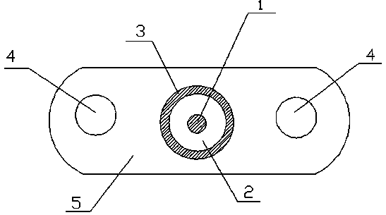
[0027] Embodiment 1: with reference to attached figure 1 , attached figure 2 , attached image 3 And attached Figure 4 .

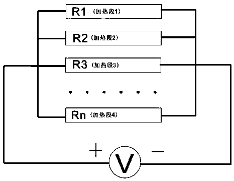
[0028] A novel composite sensing optical cable, comprising carbon fiber filament 2, temperature sensing optical fiber 1, power supply wire 4, sheath 3 and insulating cladding 5. The temperature-sensing optical fiber 1 is one, and the power supply wire 4 is one pair. The carbon fiber filaments 2 are cross-connected with the surrounding power supply wires 4 to form a parallel circuit and supply power at the same time, and the carbon fiber filaments 2 will generate heat after being energized to achieve uniform heating of the optical cable over a long distance. The temperature-sensing optical fiber 1 is wrapped by the carbon fiber 2, or the temperature-sensing optical fiber 1 and the carbon fiber 2 are arranged in parallel, and the carbon fiber 2 is energized to generate heat, so that the temperature-sensing optical fiber 1 can be uniformly heated. Two ...

Embodiment 2

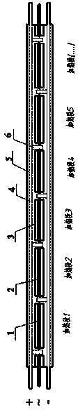
[0030] Embodiment 2: refer to Figure 5 . In this embodiment, a structural modification is carried out on the basis of Embodiment 1. Put the two temperature-sensing optical fibers 1 on the outside of the carbon fiber filament 2. The two temperature-sensing optical fibers 1 can have single-mode-multi-mode 50 / 125, multi-mode 50 / 125-multi-mode 62.5 / 125, and dual-multi-mode 50 / 125 Or multi-mode 62.5 / 125 and other combinations, and use different coating colors to distinguish. The optical cable monitors leakage through temperature changes, and some of the instruments for monitoring temperature changes use single-mode optical fibers, and some use multi-mode optical fibers. Therefore, the above combinations are adopted for the requirements of different instruments for optical fibers. Adapt to different types of fiber optic temperature measuring instruments to ensure that it can meet the temperature measurement needs of different instruments and improve their compatibility. Generall...

Embodiment 3

[0031] Embodiment 3: refer to Image 6 . This embodiment is modified on the basis of embodiment 1. The vertical cross-section of the insulating cladding of the sensing optical cable is designed to be circular, which facilitates the laying of the optical cable in buried projects and prevents the optical cable from being torsionally damaged.


PUM

PropertyMeasurementUnit
Diameteraaaaaaaaaa

Abstract

The invention discloses a novel composite sensing optical cable comprising a carbon fiber filament, temperature-sensitive fibers, power supply wires, a sheath, and an insulating wrapping layer. The carbon fiber filament, the temperature-sensitive fibers, the power supply wires, and the sheath are wrapped in the insulating wrapping layer. The carbon fiber filament is wrapped in the sheath. More than one temperature-sensitive fiber and a pair of the power supply wires are provided. The carbon fiber filament and the surrounding power supply wires are in crossed connection so as to form a parallel circuit. Power is supplied simultaneously such that the optical cable is uniformly heated at long distance by means of a fact that the carbon fiber filament generates heat after being supplied with power. The temperature-sensitive fibers are wrapped in the carbon fiber filament or arranged in parallel with the carbon fiber filament. The carbon fiber filament is heated after being supplied with power so as to uniformly heat the optical cable. Temperature measurement at various points along the cable is achieved by means of distributed fiber temperature measurement technology. The optical cable can be uniformly heated for long distance (more than 2km) and long-distance leakage can be detected.

Description

technical field [0001] The invention relates to a new type of sensing medium, in particular to a new type of sensing optical cable which can be used for monitoring dam leakage, oil and gas leakage, water pipe leakage, underground water flow and water content of rock and soil. technical background [0002] Distributed optical fiber temperature measurement technology (DTS) uses optical cable as the detection device, which has the advantages of distributed measurement, long test distance, simple construction and high long-term stability. It has been widely used in fire fighting, cable temperature measurement, concrete temperature measurement and In fields such as leakage monitoring, in order to obtain better monitoring results, various functional optical cables with specific sensing characteristics are constantly inventing and creating. [0003] The use of distributed temperature measurement technology for leakage monitoring has been applied in some engineering projects, but th...

Claims


Application Information

Patent Timeline
IPC IPC(8): H01B11/22
Inventor 魏广庆施斌李书华许凤高卢俊武张黎亮
Owner SUZHOU NANZEE SENSING TECH
Why Eureka
Try Eureka