
Multi-axis multi-speed motor

A motor and axial technology, applied in the mechanical field, can solve the problems of unsatisfactory use effect and efficiency, and the inability to fully utilize the output mechanical power, and achieve the effects of low noise, simple structure and flexible application

Active Publication Date: 2016-10-12
玉环米迪科技有限公司
View PDF5 Cites 0 Cited by
  • Summary
  • Abstract
  • Description
  • Claims
  • Application Information

AI Technical Summary

Problems solved by technology

However, the motor can only adjust the speed of the motor shaft, but cannot adjust the output shaft at different speeds. Therefore, when in use, its output mechanical power cannot be fully utilized, and the use effect and efficiency are not ideal.

Method used


Image

  • Multi-axis multi-speed motor
  • Multi-axis multi-speed motor
  • Multi-axis multi-speed motor

Examples


Embodiment 1

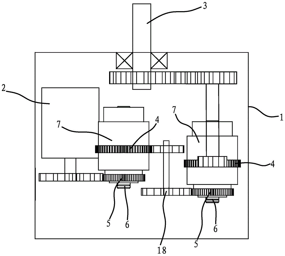
[0031] Such as figure 1 , as shown, the multi-shaft multi-speed motor includes a cylindrical shell 1, the shell 1 is provided with a motor 2 and a transmission 7, and one end of the shell 1 is axially fixed with an output shaft 3. The transmission 7 includes a cylindrical output end 4, an input end 5 and a central shaft 6 fixed axially in the cavity of the output end 4, the output end 4, the input end 5 and the central shaft 6 are coaxially arranged and the input end 5 It can drive the output end 4 to rotate around the central axis 6 , the input end 5 is connected to the rotating shaft of the motor 2 through gear transmission, and the output end 4 is connected to the output shaft 3 through transmission.

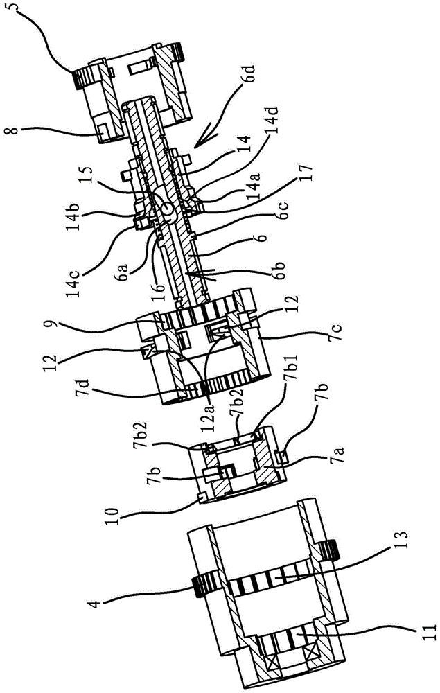
[0032] Such as image 3 and 4 As shown, more specifically, the multi-shaft multi-speed motor also includes a speed regulating mechanism 6d capable of adjusting the output end 4 at different speeds. The cavity of the output end 4 is also provided with a planet wheel frame 7...

Embodiment 2

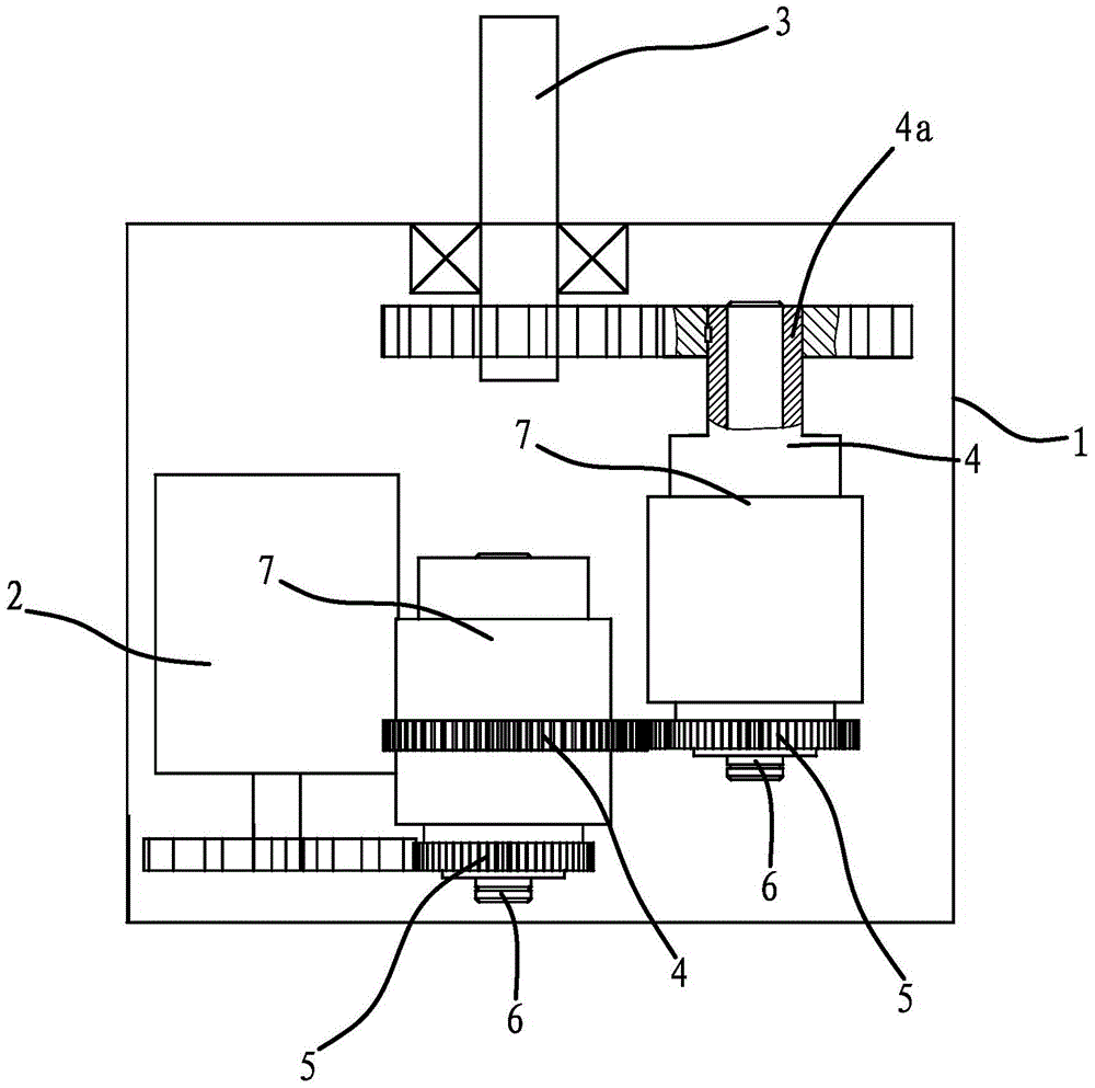
[0040] The structure and characteristics of the multi-axis multi-speed motor of the present embodiment are basically the same as those of the first embodiment, the difference being that the transmission directions of the two speed changers 7 are reversed, figure 2 As shown, the two transmissions 7 are directly connected through gears, that is, the output end 4 of the transmission 7 connected to the rotating shaft of the motor 2 is connected with the input end 5 of the other transmission 7 through gear transmission. The output end 4 of the speed changer 7 connected to the output shaft 3 is fixedly connected with the hollow shaft 4a coaxially arranged therewith, the central shaft 66 is embedded in the cavity of the hollow shaft 4a, and the hollow shaft 4a and the output shaft 3 are passed through a gear Drive connection.

Embodiment 3

[0042] The structure and characteristics of the multi-axis multi-speed motor of this embodiment are basically the same as those of Embodiment 1, the difference is that the speed regulating mechanism includes a drive motor capable of driving the central shaft to rotate, and the central shaft is connected to the inner thread of the clutch sleeve. When in use, the casing of the driving motor is positioned on the casing, and the clutch sleeve is driven to and fro by the forward and reverse rotation of the motor, which has the advantages of simple structure and convenient clutching.


PUM


Abstract

The invention provides a multi-axis and multi-speed motor, which belongs to the technical field of machinery. It solves the problem that the existing motor cannot make the output shafts have different rotating speeds. The multi-shaft and multi-speed motor includes a cylindrical casing, in which a motor is arranged, and an output shaft is fixedly connected to one end of the body in the axial direction, and a transmission is also provided in the casing, and the transmission includes a cylindrical output end, an axial The input end, the central shaft, the output end, the input end and the central shaft fixed in the cavity of the output end are coaxially arranged and the input end can drive the output end to rotate around the central axis, the input end is connected to the rotating shaft of the motor, and the output end is connected to the The output shaft is connected by transmission, and the multi-shaft multi-speed motor also includes a speed regulating mechanism capable of adjusting the output end at different speeds. The multi-shaft multi-speed motor has the advantages that the output shafts can be at different rotational speeds and the use efficiency is high.

Description

technical field [0001] The invention belongs to the technical field of machinery and relates to a motor, in particular to a multi-axis and multi-speed motor. Background technique [0002] The electric motor is a kind of rotating electric component, which converts electrical energy into mechanical energy, and is an important driving element. The electric motor is widely used in machine tools and electric bicycles. It should be selected according to the motor power required by the actual application, and try to make the motor run under the rated load. When choosing a motor, you should pay attention to the following two points: If the power of the motor is too small, the phenomenon of "small horse-drawn cart" will appear, causing the motor to be overloaded for a long time, causing its insulation to be damaged due to heat, and even the motor is burned; If the selection is too large, the phenomenon of "big horse and small cart" will appear, the output mechanical power cannot be ...

Claims


Application Information

Patent Timeline
Patent Type & Authority Patents(China)
IPC IPC(8): H02K7/116F16H3/44F16H63/00F16D23/00F16H57/08
Inventor 林扬帜
Owner 玉环米迪科技有限公司
Learn More