

Heat resistance and conduction structure of bearing for medical imaging equipment
A technology of medical imaging and heat conduction resistance, applied in the field of bearings, can solve the problem of short service life of bearings, and achieve the effect of extending the service life, reducing the temperature and improving the lubrication performance.
- Summary
- Abstract
- Description
- Claims
- Application Information
AI Technical Summary
Problems solved by technology
Method used
Image


Examples
Embodiment 1
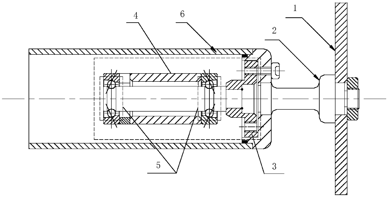
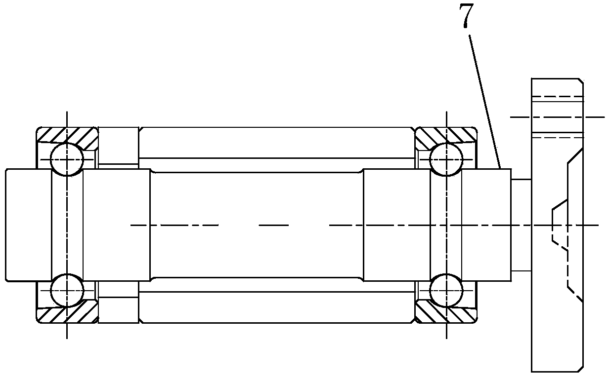
[0037] see Figure 6 , the heat-resistance structure of the bearing used for the X-ray tube of medical imaging equipment, including the main bearing part 100, the bearing neck 200, and the bearing flange 300, and a hollow heat dissipation column 400 extending from one side of the bearing flange toward the main part of the bearing , the hollow cooling column 400 is connected with the bearing neck 200 , and the bearing neck 200 is connected with the main bearing part 100 . The bearing flange 300 is provided with a bolt connection hole 310 to facilitate connection with the flange of the molybdenum rod, and the bolt connection hole is located outside the hollow cooling column. The contact area between the end face 320 of the bearing flange and the flange of the molybdenum rod is reduced.
[0038] see Figure 7 , the cross-sectional structure of the side wall of the hollow cooling column is a combination structure of several layers of thin walls 410 arranged in a zigzag shape. I...
Embodiment 2
[0046] Figure 8Shown is the heat-resistance and conduction structure of the bearing for the CT machine ball tube of the medical imaging equipment, and its structural principle is consistent with that in Embodiment 1. It includes the main part of the bearing, the neck of the bearing, and the flange of the bearing. On one side of the flange of the bearing, a hollow cooling column is extended toward the main part of the bearing. The hollow cooling column is connected to the neck of the bearing, and the neck of the bearing is connected to the main part of the bearing. . There are bolt connection holes on the bearing flange to facilitate the connection with the flange of the molybdenum rod. The bolt connection hole is located on the outer side of the hollow cooling column. The cross-sectional structure of the side wall of the hollow cooling column is a combination structure of three layers of thin walls arranged in a zigzag.
Embodiment 3
[0048] Figure 9 Shown is a schematic diagram of another bearing heat resistance structure.
[0049] The cross-sectional structure of the side wall of the hollow cooling column is a combination structure of three layers of thin walls arranged in a zigzag. The minimum conduction cross-sectional area is in the innermost layer, its outer circle is φ16.4mm, and its inner hole is φ13.4mm.
[0050] Cross-sectional area: [ ( 16.4 2 ) 2 - ( 13.4 2 ) 2 ] · π = 70.179 mm 2
[0051] Note: It has a 4-φ5 perforation 420 in the middle of the outer diameter, so the cross-sectional area of the 4-φ5 hole should be removed at the minimum...
PUM
| Property | Measurement | Unit |
|---|---|---|
| Thickness | aaaaa | aaaaa |
| Thickness | aaaaa | aaaaa |
Abstract
Description
Claims
Application Information