Femtosecond laser two-photon fluorescent biological microimaging system and imaging method thereof

A two-photon fluorescence and femtosecond laser technology, which is applied in fluorescence/phosphorescence, material excitation analysis, material analysis through optical means, etc., can solve the problems of generating two-photon fluorescence signals, unable to excite samples, and unable to complete imaging of samples, etc. Achieve low-cost results

Active Publication Date: 2014-12-10
HARBIN INST OF TECH
View PDF4 Cites 32 Cited by
  • Summary
  • Abstract
  • Description
  • Claims
  • Application Information

AI Technical Summary

Problems solved by technology

The influence of the external environment can easily cause the femtosecond laser to lose lock, and the laser cannot excite the sample to generate two-photon fluorescenc

Method used


Image

  • Femtosecond laser two-photon fluorescent biological microimaging system and imaging method thereof
  • Femtosecond laser two-photon fluorescent biological microimaging system and imaging method thereof
  • Femtosecond laser two-photon fluorescent biological microimaging system and imaging method thereof

Examples


specific Embodiment approach 1

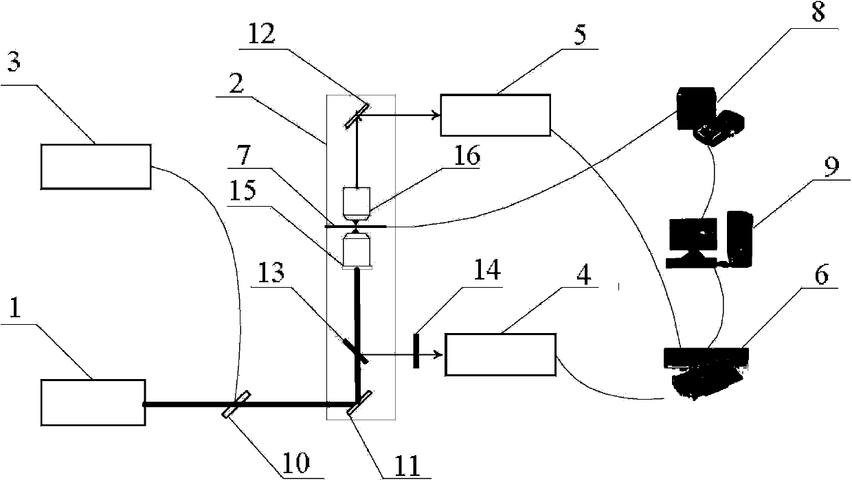
[0033] Specific implementation mode one: combine image 3 Describe this embodiment, a femtosecond laser two-photon fluorescence biomicroscopic imaging system, characterized in that: the system includes: tunable femtosecond laser source Tsunami (1), biological microscope (2), spectrometer (3), Photomultiplier tube (4), photodiode (5), data acquisition card (6), electric translation stage (7), electric translation stage controller (8), computer (9) and beam splitter (10); The biological microscope (2) includes a mirror M1 (11), a mirror M2 (12), a dichroic mirror (13), an emission filter (14), an objective lens (15) and a light collector (16);

[0034] The laser light generated by the tunable femtosecond laser source Tsunami (1) splits the laser light through a beam splitter (10), and enters the biological microscope (2) and spectrometer (3) respectively, and the spectrometer (3) is used to monitor the tunable The working state of the femtosecond laser source Tsunami (1), the l...

specific Embodiment approach 2

[0045] Specific embodiment two: this embodiment differs from specific embodiment one in that: the emission filter (14) is made of a band-pass filter and an infrared cut-off filter, and the band-pass filter is located near the dichroic mirror (13) On one side, the infrared cut-off filter is located on the side close to the photomultiplier tube (4).

specific Embodiment approach 3

[0046] Embodiment 3: The difference between this embodiment and Embodiment 1 or 2 is that the laser generated by the tunable femtosecond laser source Tsunami is an ultrashort pulse with a center wavelength of 800 nm, a repetition frequency of 82 MHz, and a pulse width of 50 fs Mode-locked laser.


PUM

PropertyMeasurementUnit
Center wavelengthaaaaaaaaaa
Pulse widthaaaaaaaaaa

Abstract

The invention relates to a femtosecond laser two-photon fluorescent biological microimaging system and an imaging method thereof, and aims at solving the problem that the cost is high and the imaging speed requirements cannot be met in an existing two-photon fluorescent microscope. A femtosecond laser device is easily unlocked due to the influence of external environment, and the unlocked laser device cannot excite a sample to generate a two-photon fluorescent signal; the two-photon fluorescent microimaging is imaging on the specific components of the sample and not complete imaging on the sample. The femtosecond laser two-photon fluorescent biological microimaging system is characterized by comprising a tunable femtosecond laser source Tsunami (1), a biological microscope (2), a spectrometer (3), a photomultiplier (4), a photodiode (5), a data acquisition card (6), an electrical translation platform (7), an electrical translation platform controller (8), a computer (9) and a beam splitting piece (10), wherein the biological microscope (2) comprises a reflection mirror M1 (11), a reflection mirror M2 (12), a dichroic mirror (13), an emission filter (14), an objective lens (15) and a condenser (16). The femtosecond laser two-photon fluorescent biological microimaging system is applied in the field of fluorescent microimaging.

Description

technical field [0001] The invention relates to a femtosecond laser two-photon fluorescence biomicroscopic imaging system and an imaging method thereof. Background technique [0002] Fluorescence is a luminescence phenomenon in which certain substances emit a wavelength greater than the excitation wavelength in a very short period of time after being excited by light of a certain wavelength. In the middle of the nineteenth century, the British scientist G. Stokes first observed the fluorescence phenomenon by using ultraviolet light to irradiate fluorite minerals. However, it was not until the 1930s that the Austrian scientist M. Haitinger and other talents introduced fluorescent labeling technology into the field of life sciences. , who used fluorescent dyes to label specific components such as bacteria and viruses, which promoted the development of fluorescence microscopy. [0003] The basic working principle of a fluorescence microscope is to irradiate a sample marked wit...

Claims


Application Information

Patent Timeline
IPC IPC(8): G01N21/64G01N21/01
Inventor 夏元钦秦一凡杨兆辉李茜张盛刘斌赵阳
Owner HARBIN INST OF TECH
Why Eureka
Try Eureka