Demodulator circuit

A technology of demodulation circuit and comparison circuit, which is applied in the field of demodulation, and can solve the problems of low-frequency carrier amplitude fluctuation and obvious changes in the envelope detection circuit

Inactive Publication Date: 2014-12-10
HEFEI NINGXIN ELECTRONICS TECH
View PDF4 Cites 20 Cited by
  • Summary
  • Abstract
  • Description
  • Claims
  • Application Information

AI Technical Summary

Problems solved by technology

[0007] In the process of implementing the present invention, the inventor found that in a passive RFID system, since the strength of the electromagnetic field where the RFID tag chip is located usually changes, the highest voltage sensed by the antenna of the RFID tag chip will also constantly change. , and the signal strength received by the antenna changes significantly with the distance factor, which will cause the amplitude of the low-frequency carrier wave obtained by the envelope detection circuit to fluctuate greatly; at the same time, in high-speed data communication, the signal detected by the envelope detection circuit The waveform needs to change rapidly following the change of the modulating signal; therefore, when the existing envelope detection method is applied to the passive RFID system, the accuracy of the demodulated signal needs to be further improved

Method used


Image

  • Demodulator circuit
  • Demodulator circuit
  • Demodulator circuit

Examples


Embodiment Construction

[0030] In order to further explain the technical means and effects of the present invention to achieve the intended purpose of the invention, the specific implementation, structure, characteristics and effects of the demodulation circuit proposed according to the present invention will be described below in conjunction with the accompanying drawings and preferred embodiments. Details are as follows.

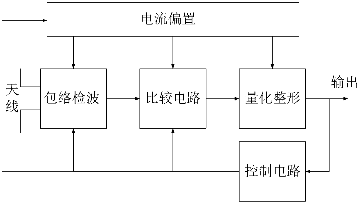
[0031]The structure of the demodulation circuit for demodulating the ASK signal in the embodiment of the present invention is as follows: figure 2 shown.

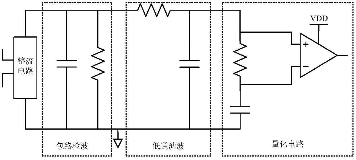
[0032] figure 2 The demodulation circuit mainly includes: bias circuit (ie figure 2 The current bias in), the envelope detector circuit (ie figure 2 Envelope detection in), comparison circuit, shaping circuit (can also be called quantization shaping circuit, namely figure 2 Quantization shaping in) and control circuit. Optionally, the demodulation circuit may further include: a global switch. Each part of the demodu...


PUM


Abstract

The invention relates to a demodulator circuit. The demodulator circuit comprises a biasing circuit, an envelope detection circuit, a comparison circuit, a shaping circuit and a control circuit, wherein the envelope detection circuit comprises a full-wave rectification circuit and a band-pass filter, the full-wave rectification circuit is used for rectifying a full-wave alternating current signal which is received by an antenna to a direct current signal, and the band-pass filter is used for performing band-pass filtering on the direct current signal to output an envelope signal within a preset bandwidth range; the comparison circuit is used for reducing amplitude of a carrier signal through voltage comparison of the envelope signal; the shaping circuit is used for extracting an ASK signal from signals which are output by the envelope detection circuit or the comparison circuit; the control circuit is used for generating a control signal according to the ASK signal so that the band-pass filter is controlled to perform discharging before the ASK signal jumps from a low level to a high level and the comparison circuit is started and the comparison circuit is controlled to be closed after the ASK signal jumps from the high level to the low level. The demodulator circuit can be excellently applied to a passive radio frequency identification (RFID) system, and the accuracy of a demodulated signal is good.

Description

technical field [0001] The invention relates to demodulation technology, in particular to a demodulation circuit suitable for demodulation of ASK signals. Background technique [0002] At present, radio frequency identification (Radio Frequency Identification, RFID) technology has been widely used in various fields such as commodity circulation, manufacturing, and item and personnel tracking. [0003] The data interaction process based on Amplitude Shift Keying (ASK) is usually: the reader performs 10% or 100% ASK modulation on the data to form an ASK signal, and the ASK signal is transmitted through electromagnetic waves, and the RFID tag chip enters the reading After the launch field of the reader, the data is demodulated from the received ASK signal, so as to successfully receive the data sent by the reader (such as commands, etc.). [0004] Currently, demodulation methods for 100% ASK modulated ASK signals mainly include: a coherent demodulation method and an envelope d...

Claims


Application Information

Patent Timeline
Patent Type & Authority Applications(China)
IPC IPC(8): G06K19/077H03F3/45
Inventor 吴秀龙蔺智挺李正平陈军宁彭春雨汪坤
Owner HEFEI NINGXIN ELECTRONICS TECH
Why Eureka
Try Eureka