
Integrated cooling device of silicon-based micro-channel radiator

A cooling device and micro-channel technology, which is applied in electric solid-state devices, semiconductor devices, semiconductor/solid-state device components, etc., can solve the problems of silicon-based micro-channel heat dissipation technology patents, etc., and achieve good expansion coefficient matching and heat dissipation efficiency. Increased, versatile effect

Inactive Publication Date: 2014-12-10
SOUTHWEST CHINA RES INST OF ELECTRONICS EQUIP
View PDF7 Cites 24 Cited by
  • Summary
  • Abstract
  • Description
  • Claims
  • Application Information

AI Technical Summary

Problems solved by technology

At present, there are many patents on micro-channel heat dissipation technology, and patents on micro-machining technology on silicon substrates are also extensive, but the combination of the two-the patents on silicon-based micro-channel heat dissipation technology are very few, only CN1558448A, CN103839905A, etc.

Method used


Image

  • Integrated cooling device of silicon-based micro-channel radiator
  • Integrated cooling device of silicon-based micro-channel radiator
  • Integrated cooling device of silicon-based micro-channel radiator

Examples


Embodiment 1

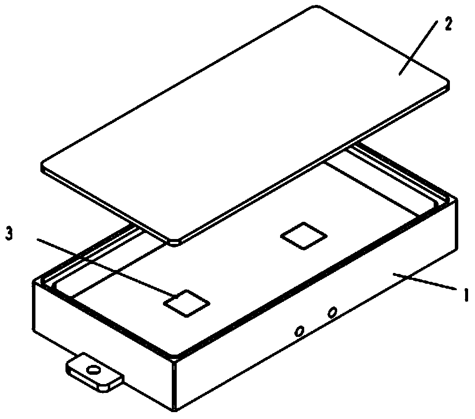
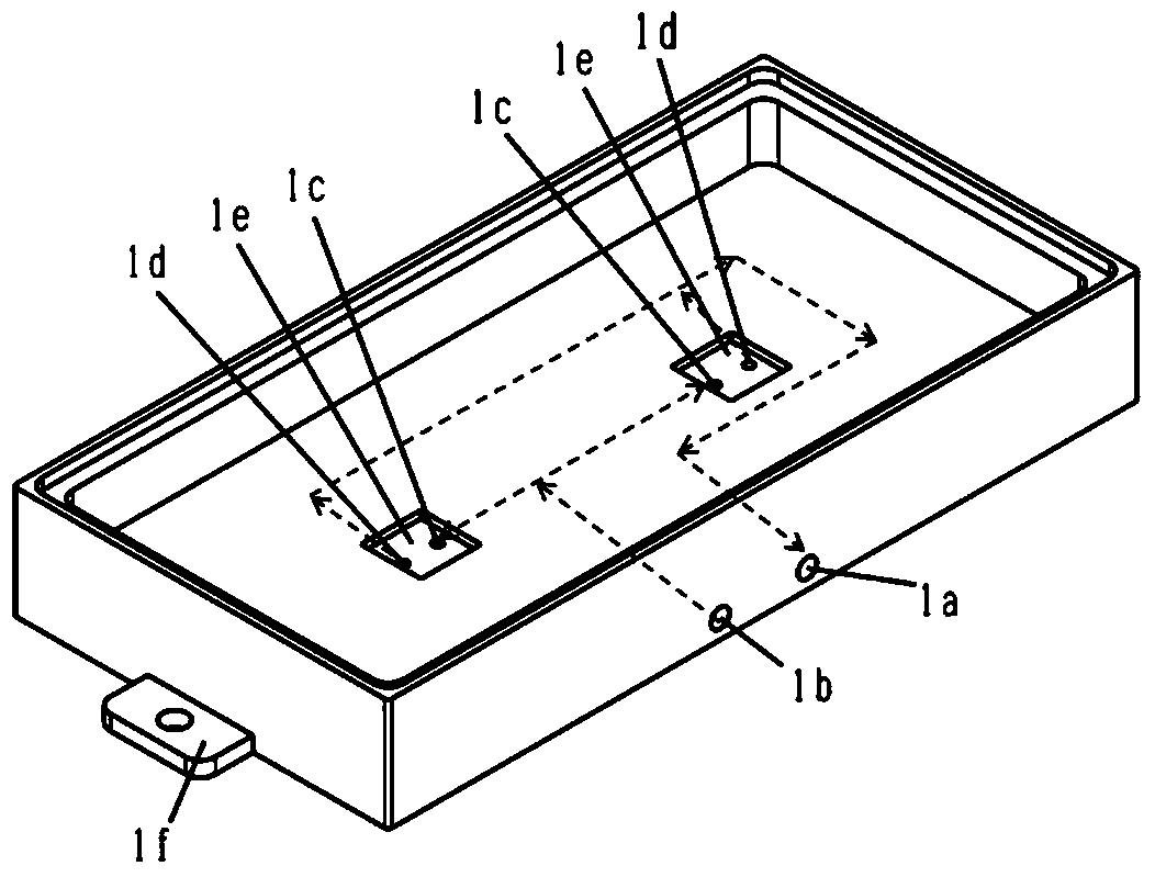
[0024] Such as figure 1 As shown, the peripheral dimensions of the silicon-based microchannel radiator integrated cooling device in this embodiment are 50mm (length) × 50mm (width) × 20mm (height), consisting of a box body, a silicon-based microchannel radiator, and a cover plate three Partial composition. The box body is a cavity with an open upper end, a flow channel is arranged inside the bottom plate of the box body, the inlet and outlet of the unit cooling liquid and the external opening of the internal electronic chip are arranged on the outer side of the box body, and mounting ears are arranged on the outer side of the box body for integrated cooling. External connection of the device.

[0025] Four small grooves are set on the bottom plate of the box body, and the silicon-based micro-channel radiator is installed in the small groove. The road is connected. The flow channel at the bottom of the box distributes the cooling liquid to the inlet of each silicon-based mic...

Embodiment 2

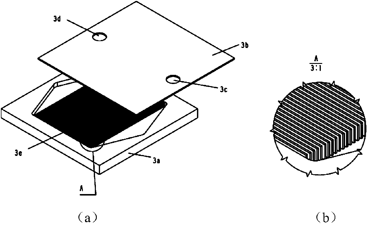
[0040] Such as figure 2 As shown, the peripheral dimension of the silicon-based microchannel radiator integrated cooling device is φ80mm×20mm, the size of the silicon-based microchannel radiator is 10mm×10mm×1.3mm, the flow channel is linear, the fin thickness is 0.08mm, and the fin The spacing is 0.06mm, and the inlet and outlet are round holes with a diameter of 1.2mm. The heat dissipation system is equipped with 4 silicon-based microchannel radiators. The cooling liquid inlet and outlet interface of the system is M3×0.35mm in size, located at the bottom of the device, and the diameter of the internal flow channel is 3mm.


PUM


Abstract

The invention provides an integrated cooling device of a silicon-based micro-channel radiator, which is composed of a box body, a silicon-based micro-channel radiator and a cover plate. The box body is a cavity with an opening at the upper end; a flow channel is arranged inside the bottom plate of the box body; a unit cooling liquid inlet and outlet, and an externally connected opening of an internal electronic chip are arrange on the outer side face of the box body; multiple small grooves are formed in the bottom plate of the box body; the silicon-based micro-channel radiator is arranged in the small grooves; two openings are formed in the bottom of each small groove to realize communication between the cooling liquid inlet and outlet of the silicon-based micro-channel radiator and the flow channel at the bottom of the box body; the silicon-based micro-channel radiator is composed of a silicon bottom plate and a silicon cover plate; radiating fins are formed on the silicon bottom plate; both the thickness of the fins and the distance among the fins are less than 0.1 mm. Through such the integration way, the radiator can be arranged and expanded based on the number and positions of high heating flux density chips, the disadvantage that the silicon-based radiator cannot be enlarged is overcome, and strong universality is achieved.

Description

technical field [0001] The invention belongs to the technical field of heat dissipation of electronic equipment, in particular to a silicon-based microchannel radiator integrated cooling device. Background technique [0002] For power electronic systems with high heat flux density, liquid cooling is often used to dissipate heat, such as liquid-cooled chassis and liquid-cooled modules. These traditional liquid cooling and heat dissipation methods usually use copper, aluminum and other materials to make liquid flow channels, and then seal and weld them to form radiators. The size of the flow channels is usually above 1mm. Between the radiator and the chip, there is usually a problem that the thermal expansion coefficient of the radiator material does not match that of the chip material. The conventional method is to relieve the thermal expansion stress by soldering transitional plates such as molybdenum copper sheets, which undoubtedly increases the heat dissipation from the c...

Claims


Application Information

Patent Timeline
Patent Type & Authority Applications(China)
IPC IPC(8): H01L23/367H01L23/373
Inventor 王延尹本浩祁成武
Owner SOUTHWEST CHINA RES INST OF ELECTRONICS EQUIP
Learn More