Eureka AIR delivers breakthrough ideas for toughest innovation challenges, trusted by R&D personnel around the world.

Manufacturing method for infrared light emitting diode with embedded extended electrode

An extended electrode, infrared light-emitting technology, applied in circuits, electrical components, semiconductor devices, etc., can solve the problems of floating electrodes, side erosion, easy to fall off, etc., to reduce the light blocking area, increase the light emitting area, and avoid side erosion. Effect

Inactive Publication Date: 2014-12-10
XIAMEN CHANGELIGHT CO LTD
View PDF4 Cites 10 Cited by
  • Summary
  • Abstract
  • Description
  • Claims
  • Application Information

AI Technical Summary

Problems solved by technology

[0004] The purpose of the present invention is to provide a method for manufacturing an infrared light-emitting diode with embedded extended electrodes, to solve the problem that the traditional manufacturing process easily causes the side erosion of the epitaxial layer under the extended electrodes, causing the extended electrodes to be suspended and easy to fall off. Light-emitting diodes get better current expansion effect, improve luminous efficiency and reliability

Method used


Image

  • Manufacturing method for infrared light emitting diode with embedded extended electrode
  • Manufacturing method for infrared light emitting diode with embedded extended electrode
  • Manufacturing method for infrared light emitting diode with embedded extended electrode

Examples


Embodiment Construction

[0053] The present invention will be described in detail below in conjunction with the accompanying drawings and specific embodiments.

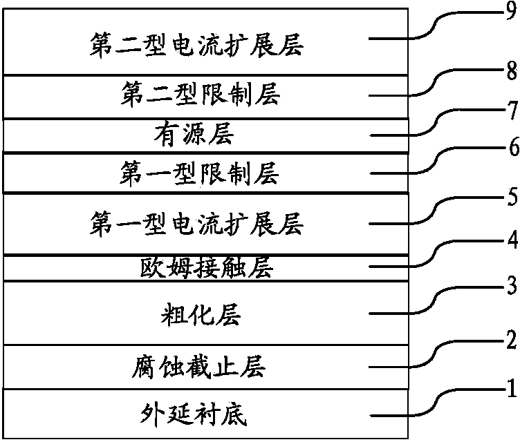
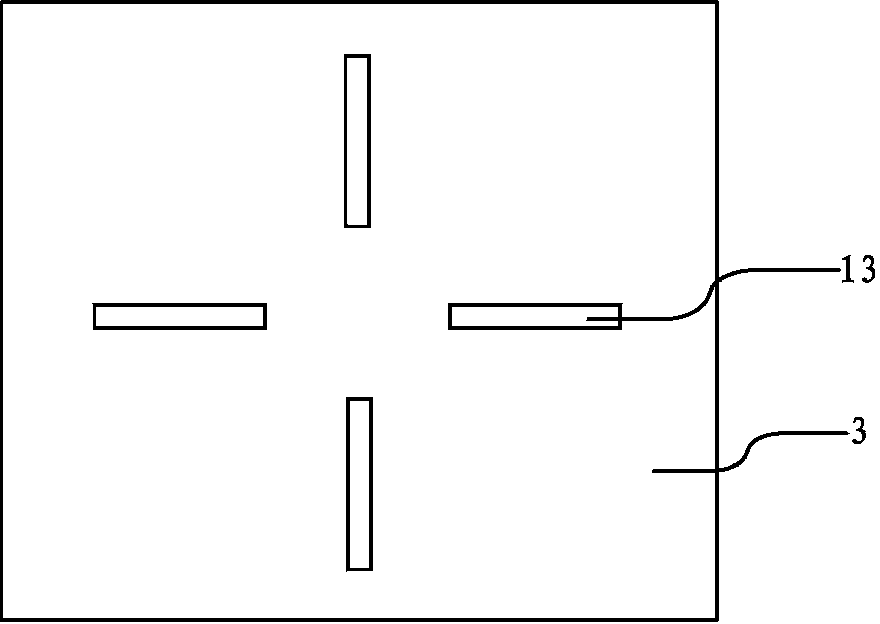
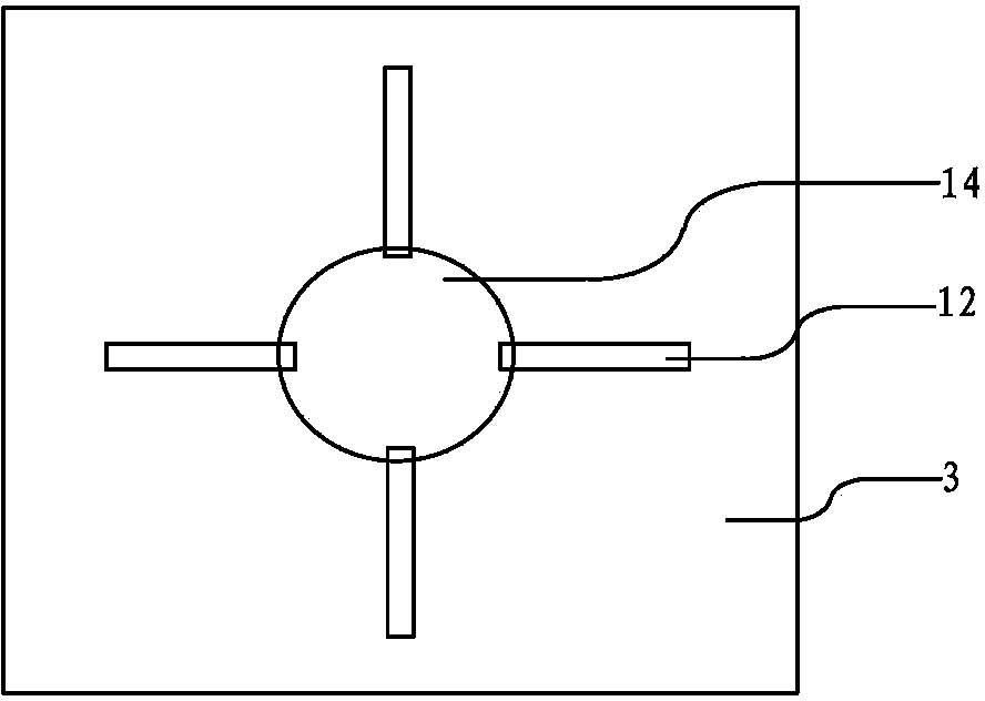
[0054] refer to Figure 1 to Figure 4 As shown, the first embodiment of an infrared light-emitting diode with embedded extended electrodes disclosed by the present invention; figure 1 It is an epitaxial structure of an infrared light emitting diode, and the epitaxial structure is an intermediate body for making an infrared light emitting diode with an embedded extended electrode.

[0055] The epitaxial structure includes an etching stop layer 2, a roughening layer 3, an ohmic contact layer 4, a first-type current spreading layer 5, a first-type confinement layer 6, and an active layer 7 on the upper surface of an epitaxial substrate 1 from bottom to top. , the second-type confinement layer 8 and the second-type current spreading layer 9 .

[0056] Wherein, the epitaxial substrate 1 is a GaAs substrate with a thickness of 300 μm. The materi...


PUM


Abstract

The invention discloses a manufacturing method for an infrared light emitting diode with an embedded extended electrode. The manufacturing method for the infrared light emitting diode with the embedded extended electrode includes that forming a corrosion resisting layer, an armoring layer, an ohmic contact layer, a first current extension layer, a first limit layer, an active layer, a second limit layer and a second current extension layer on an epitaxial substrate in sequence; forming a metal reflector layer on the second current extension layer through evaporation; bonding a metal reflecting layer to a base plate; removing the epitaxial substrate and corrosion resisting layer to expose the armoring layer; forming an extended electrode pattern channel in the surface of the armoring layer, wherein the channel is deep enough to expose the ohmic contact layer; evaporating metal material in the channel to form the extended electrode; manufacturing a bonding pad electrode at the surface of the armoring layer, and communicating the bonding pad electrode with the extended electrode; evaporating a back electrode at the back of the base plate, removing protecting layers of the bonding pad electrode and extended electrode, and shredding to obtain the infrared light emitting diode with the embedded extended electrode. The manufacturing method for the infrared light emitting diode with the embedded extended electrode is capable of improving the reliability of the extended electrode, obtaining better current extension effect and improving the light emitting efficiency of the infrared light emitting diode.

Description

technical field [0001] The invention relates to the technical field of light-emitting diodes, in particular to a method for manufacturing an infrared light-emitting diode with embedded extended electrodes. Background technique [0002] Infrared light-emitting diodes have the advantages of low power consumption, small size and high reliability, and are widely used in communication, remote sensing devices and other fields. In the prior art, metal-organic compound vapor phase epitaxy is used to grow the epitaxial structure with quantum wells to achieve higher internal quantum efficiency; at the same time, flip-chip manufacturing processes such as metal mirrors and surface roughening are used to improve the external quantum efficiency of infrared light-emitting diodes. efficiency. [0003] The flip-chip manufacturing process usually uses extended electrodes to improve the current spreading effect, so as to obtain higher luminous efficiency. However, most of the flip-chip manuf...

Claims


Application Information

Patent Timeline
Patent Type & Authority Applications(China)
IPC IPC(8): H01L33/38
CPCH01L33/38H01L33/005H01L33/405
Inventor 林志伟陈凯轩张永杨凯蔡建九白继锋卓祥景姜伟刘碧霞
Owner XIAMEN CHANGELIGHT CO LTD
Why Eureka
Eureka Blog
Learn More