A kind of LED molding sealing device and sealing method thereof

A sealing device and molding technology, which is applied in the direction of electrical components, circuits, semiconductor devices, etc., can solve the problems of packaging glue sticking to the mold, reducing the yield of molded products, and residual air bubbles in sealing glue products, so as to ensure the integrity of the glue, Increased yield and reduced thermal stress

Inactive Publication Date: 2016-07-06
GUANGDONG VTRON TECH CO LTD
View PDF9 Cites 8 Cited by
  • Summary
  • Abstract
  • Description
  • Claims
  • Application Information

AI Technical Summary

Problems solved by technology

During the thermal curing process of the glue, a phase change occurs and the colloid shrinks, resulting in the loss of a large piece of colloid at the position adjacent to the glue channel (3-5) and the cavity (3-6), forming a waste area on the molded product (2-1) , reducing the yield of molded products
[0004] The sealing method of the ordinary manual molding and sealing device is to apply the film release agent on the heated mold, which is very easy to volatilize and cannot form a film on the surface of the mold, so that the cured encapsulating glue is easy to stick to the mold when demolding Due to the above situation, the sealant is incomplete as a whole, resulting in bad sealant products; moreover, the sealant products often have more or less residual air bubbles

Method used


Image

  • A kind of LED molding sealing device and sealing method thereof
  • A kind of LED molding sealing device and sealing method thereof
  • A kind of LED molding sealing device and sealing method thereof

Examples


Embodiment 1

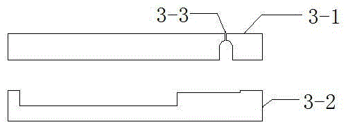
[0040] A LED molding and sealing device, the schematic diagram, cross-sectional view and perspective view of its components are as follows Image 6 , Figure 7 with Figure 8 As shown, it includes an upper mold 3-1, a lower mold 3-2 and a rubber channel partition structure. The upper part of the upper mold 3-1 is provided with a glue injection port 3-3, and the upper part of the lower mold 3-2 is provided with a cavity 3-6. The injection port 3-3 is connected to the cavity 3-6 through the rubber channel 3-5 arranged at the lower part of the upper mold 3-1 and the upper part of the lower mold 3-2, and the upper mold 3-1 and the lower mold 3-2 are locked After the parts are locked, it also includes the glue channel partition structure set in the glue channel 3-5. When injecting glue, the glue thrust will make the glue channel partition structure shift and connect the glue channel 3-5. When the glue injection is completed, the glue thrust will disappear. Reset the rubber channe...

Embodiment 2

[0043] In this embodiment, on the basis of embodiment 1, the rubber channel partition structure is specifically designed, and the schematic diagrams, cross-sectional views and perspective views of each component are as follows Image 6 , Figure 7 with Figure 8 As shown, the rubber channel partition structure includes an inner rubber pool 3-4, a steel ball 3-8 and an elastic member 3-9, one side of the inner rubber pool 3-4 communicates with the rubber channel 3-5, and the upper half of the inner rubber pool 3 -10 and the lower half of the inner glue pool 3-11 are correspondingly arranged on the lower part of the upper mold 3-1 and the upper part of the lower mold 3-2, and the top of the inner glue pool 3-4 is provided with an opening communicating with the injection port 3-3, and The opening is a spherical fitting surface 3-12, the elastic member 3-9 is arranged at the bottom of the inner rubber pool 3-4, the steel ball 3-8 is placed in the inner rubber pool 3-4 and is loca...

Embodiment 3

[0049] In this embodiment, on the basis of embodiment 2, the shape of the inner rubber pool 3-4 is improved, and replaced with a spherical cavity that is more convenient for cleaning and demoulding. Schematic diagrams and cross-sectional views of its components are shown in Figure 9 , Figure 10 As shown, the upper half 3-10 of the inner glue pool and the lower half 3-11 of the inner glue pool are hemispherical.

[0050] The working principle of this embodiment is the same as that of embodiment 2, but, compared with embodiment 2, the inner glue pool 3-4 of this embodiment is spherical, and its capacity is smaller than that of a cuboid, thereby reducing the amount of glue injected and removing It is easier to mold and clear the mold.


PUM


Abstract

The invention discloses an LED molding sealing device and a sealing method thereof. The device comprises an upper mold, a lower mold and a glue channel partition structure. The upper part of the upper mold is provided with a glue injection port, the upper part of the lower mold is provided with a cavity, and the glue injection port The cavity is connected to the mold cavity through the glue channel set on the lower part of the upper mold and the upper part of the lower mold. The upper mold and the lower mold are locked by the locking parts. It also includes the glue channel partition structure set in the glue channel. The glue channel partition structure is shifted to connect the rubber channel. When the glue injection is completed, the glue thrust disappears, and the glue channel partition structure is reset to automatically isolate the glue channel. The present invention is applicable to the LED sealing field. The present invention not only has a simple structure and is convenient to use, but also can well maintain the pressure of the glue in the mold cavity when the sealing is completed, avoiding volume shrinkage during the heat curing process of the sealing glue, and ensuring the sealing effect. The colloid of the finished product is complete, increasing the yield of the molded product.

Description

technical field [0001] The invention relates to the field of LED sealing, more specifically, to an LED molding sealing device and a sealing method thereof. Background technique [0002] With the rapid development of the LED display industry, new types of LED sealing materials are constantly emerging. With the development of high-definition screens, the resolution of indoor display screens is getting higher and higher, so indoor LED display screens are inevitably developing towards fine pitch and high density. Traditional bowl-cup dispensing packaging has become more and more difficult to meet the packaging requirements of high-density LEDs. High-density LEDs have strict requirements on the quality of sealing glue. The form of single glue dispensing is not only inefficient, but also it is difficult to guarantee the high consistency of the finished product. Molding form potting, also known as molding, can well meet the high-density LED's demand for high consistency of the se...

Claims


Application Information

Patent Timeline
Patent Type & Authority Patents(China)
IPC IPC(8): B29C45/14B29C45/28H01L33/48
CPCB29C45/14647B29C45/28H01L33/48
Inventor 佘星欣吴廷胡新禧
Owner GUANGDONG VTRON TECH CO LTD
Why Eureka
Try Eureka