Conveyor system, textile plant with same and method for starting textile plant

A technology of transmission system, textile equipment, applied in the field of transmission system

Active Publication Date: 2017-06-09
KARL EUGEN FISCHER GMBH
View PDF1 Cites 0 Cited by
  • Summary
  • Abstract
  • Description
  • Claims
  • Application Information

AI Technical Summary

Problems solved by technology

Therefore, known delivery systems do not always work satisfactorily

Method used


Image

  • Conveyor system, textile plant with same and method for starting textile plant
  • Conveyor system, textile plant with same and method for starting textile plant
  • Conveyor system, textile plant with same and method for starting textile plant

Examples


Embodiment Construction

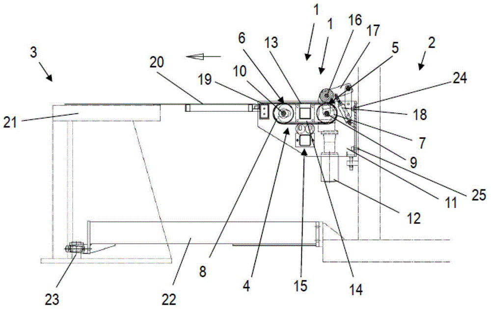
[0045] exist figure 1 A side view of the conveyor system 1 is shown in . The conveyor system 1 is located between two adjacent plant parts: the uncoiling station 2 and the cutting device 3 . In this case, the conveyor system 1, the uncoiling station 2 and the cutting device 3 are part of a textile Figure 6 and 7 is schematically shown in and is used for processing thin and sticky ply strips.

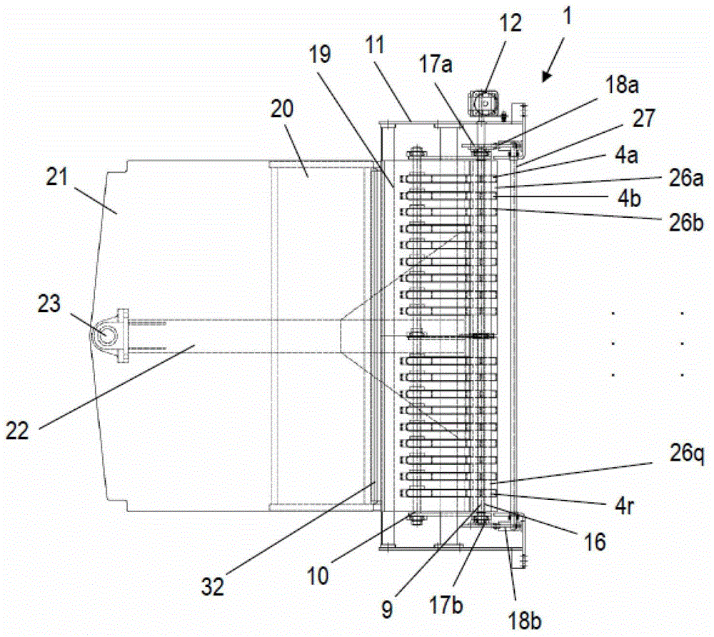
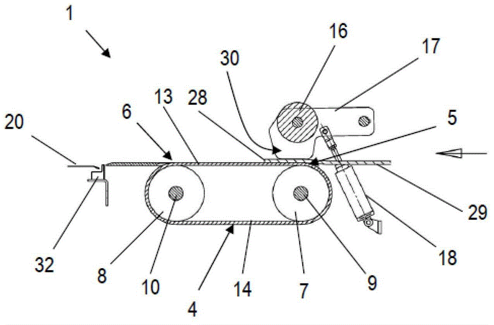
[0046] The conveyor system 1 has a plurality of conveyor belts 4 arranged parallel to one another, which are guided in a loop at a conveyor start 5 and a conveyor end 6 via deflection wheels 7 , 8 . In this case, the deflecting wheels 7 , 8 are mounted rotatably via shafts 9 , 10 in the frame 11 of the conveyor system 1 , respectively. In this case, the shaft 9 arranged at the delivery start 5 can be driven via a drive 12 . The movement of the shaft 9 is transmitted via the deflection pulley 7 to the conveyor belt 4 and to the deflection pulley 8 with its shaft 10 . The strip of m...


PUM


Abstract

The invention relates to a conveyor system (1) for a textile plant for feeding a starting end (28) of a material web (29), in particular a cohesive cord material web with textile threads and / or steel wires, from One plant part (2) is transferred to the adjacent plant part (3). In order to achieve a safe transfer of the starting point and thus a safe start-up of the textile plant, the conveyor system (1) has at least one conveyor belt (4) which is cyclically guided between a conveyor start (5) and a conveyor end (6). ), especially a plurality of conveyor belts (4) arranged parallel to each other, and a pressure roller (16) supported in a swingable manner, wherein the material strip (29) can pass through the pressure roller at the beginning of the transmission (5) Rollers (16) are pressed onto said one conveyor belt (4) or said plurality of conveyor belts (4).

Description

technical field [0001] The invention relates to a conveyor system for a textile plant for transferring a starting end (28) of a material web, in particular a web of adhesive ply material with textile threads and / or steel wires, from a plant part (2) to the adjacent equipment part (3). The invention also relates to a textile installation with such a conveyor system and a method for starting a corresponding textile installation. Background technique [0002] Textile plants are used for processing material webs, in particular adhesive ply material webs, which have textile threads and / or steel wires for reinforcement. In the cutting device of the textile machine, the material web is cut into strips, which are then spliced ​​to one another at their edges adjoining the cut edges. Splicing is a type of connection that achieves a particularly durable connection without the need for additional bonding agents. Thereby a spliced ​​endless belt is produced, as required, for example, ...

Claims


Application Information

Patent Timeline
Patent Type & Authority Patents(China)
IPC IPC(8): B65H20/06B65H20/00
Inventor 马蒂亚斯·施米特
Owner KARL EUGEN FISCHER GMBH
Why Eureka
Try Eureka