Horizontal directional drilling crossing construction method and drilling equipment

A technology of horizontal directional drilling and horizontal directional drilling rig, which is applied in the directions of directional drilling, earth-moving drilling, wellbore/well components, etc. It can solve the problem of increasing the amount of bentonite and additives, suspending and discharging drilling cuttings, and being unsuitable for horizontal directional drilling. Law and other issues to achieve the effect of protecting the environment, reducing construction risks, and reducing construction costs

Active Publication Date: 2016-08-10
BC P INC CHINA NAT PETROLEUM CORP +1
View PDF6 Cites 2 Cited by
  • Summary
  • Abstract
  • Description
  • Claims
  • Application Information

AI Technical Summary

Problems solved by technology

[0003] The weak point of above-mentioned method is: 1, in reaming and dragging back stage, borehole wall is only supported by the mud of liquid state, it is difficult to keep borehole wall stable for a long time for loose formation, and graded reaming will increase Disturbance to the formation prolongs the self-stabilization time of drilling and increases the risk of crossing failure caused by hole collapse
For pebble and gravel formations, drill cuttings with large particle sizes cannot be suspended and discharged out of the borehole, so drill sticking accidents are prone to occur, and horizontal directional drilling is not suitable for direct crossing
3. When crossing strata with high rock strength (greater than 50MPa), the cutting torque of the drilling tool is large. When the diameter of the crossing pipeline is large, it will be limited by the torque of the drilling tool, which is not suitable for horizontal directional drilling.
In order to solve this contradiction, we can only improve the performance of the mud and increase the amount of bentonite and additives, thereby increasing the construction cost

Method used


Image

  • Horizontal directional drilling crossing construction method and drilling equipment

Examples


Embodiment 1

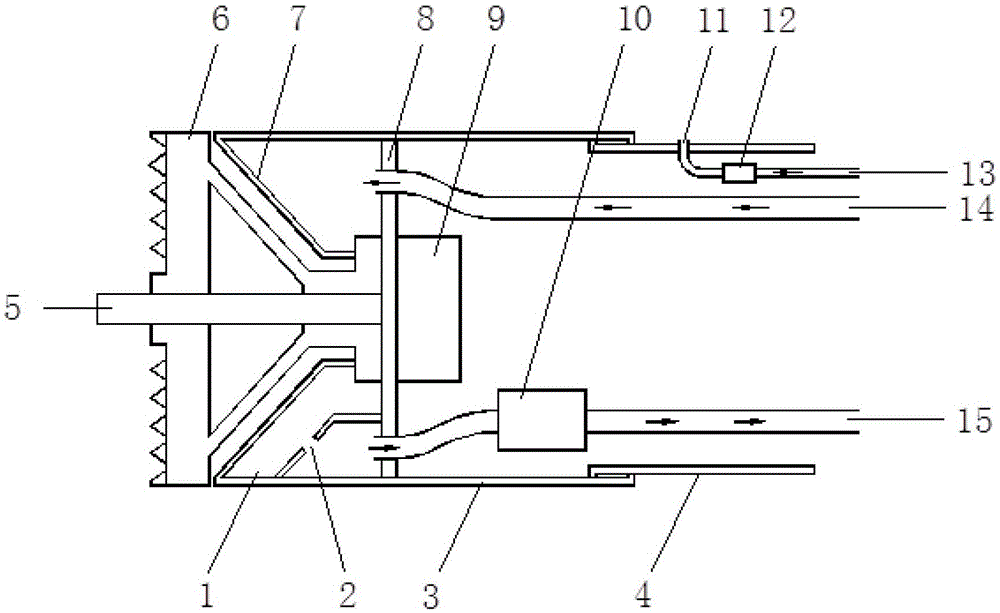
[0024] The strata traversed are silt and silty clay. First complete the preparatory work at the unearthed end. Lay water supply pipes, drainage pipes, grouting pipes and power supply lines in the crossing pipelines at the unearthed end; It is connected with the grouting pipe 13, and the crossing pipeline is welded with the pipe nipple 4 at the end of the drilling equipment. After the horizontal directional drilling machine completes the pilot hole operation, connect the drilling equipment at the excavation end. Use the horizontal directional drilling rig to pull the drill pipe, and use the drill pipe to pull the drilling equipment into the operation pit to start excavation. The drilling equipment cuts the formation to expand the drilling. The driving mechanism 9 (mud motor) drives the cutter head 6 to cut the formation, and the high-pressure mud required by the mud motor is provided by the horizontal directional drilling machine through the drill pipe. The mud is ejected f...

Embodiment 2

[0026] The strata traversed are silt sand, fine sand, medium sand and coarse sand. First complete the preparatory work at the unearthed end. Lay water supply pipes, drainage pipes, grouting pipes and power supply lines in the crossing pipelines at the unearthed end; It is connected with the grouting pipe 13, and the crossing pipeline is connected with the pipe nipple 4 at the end of the drilling equipment. After the horizontal directional drilling machine completes the pilot hole operation, connect the drilling equipment at the excavation end. Use the horizontal directional drilling rig to pull the drill pipe, and use the drill pipe to pull the drilling equipment into the operation pit to start excavation. The drilling equipment cuts the formation to expand the drilling. The driving mechanism 9 (mud motor) drives the cutter head 6 to cut the formation, and the high-pressure mud required by the mud motor is provided by the horizontal directional drilling machine through the ...

Embodiment 3

[0028] The strata traversed are silt sand, fine sand, medium sand and coarse sand. First complete the preparatory work at the unearthed end. Lay water supply pipes, drainage pipes, grouting pipes and power supply lines in the crossing pipelines at the unearthed end; It is connected with the grouting pipe 13, and the crossing pipeline is connected with the pipe nipple 4 at the end of the drilling equipment. After the horizontal directional drilling machine completes the pilot hole operation, connect the drilling equipment at the excavation end. Use the horizontal directional drilling rig to pull the drill pipe, and use the drill pipe to pull the drilling equipment into the operation pit to start excavation. The drilling equipment cuts the formation to expand the drilling. The drive mechanism 9 (motor) drives the cutter head 6 to cut the formation, and the motor is powered by the ground power supply device through the power supply line. The muddy water is injected by the wat...


PUM


Abstract

The invention discloses a horizontal directional drilling crossing construction method and drilling equipment thereof, which are designed for improving the stability of the borehole wall and reducing the crossing construction risk. The main body of the drilling equipment body is connected to the main shaft, cone crushing mechanism, cutter head and horizontal directional drilling rig in front of the cabin wall, and the cutter head drive mechanism, water supply pipe and drainage pipe are connected to the back of the cabin wall. The rear end of the body is connected with grouting There is a pipe nipple for the grouting pipe inside the hole, and the rear end of the pipe nipple is connected to the crossing pipeline. The invention is used for horizontal directional drilling of pipelines with a diameter of more than 400mm. It can expand the borehole to the size of the hole at one time and directly drag the pipeline back into the borehole to complete the laying, and at the same time fill the gap between the inner wall of the borehole and the crossing pipeline. , to discharge the cuttings to the excavation end. The invention can improve the stability of the borehole wall, reduce the construction risk caused by the collapse of the hole, reduce the construction cost, protect the environment, realize the large-diameter and long-distance pipeline crossing under the condition of loose stratum and hard rock stratum, and expand the level The scope of application of directional drilling method.

Description

technical field [0001] The invention relates to a horizontal directional drilling crossing construction method and drilling equipment thereof, belonging to the technical field of trenchless crossing construction. Background technique [0002] At present, the construction technology of horizontal directional drilling for crossing pipelines with a diameter of more than 400mm is divided into three stages: drilling pilot hole, reaming and dragging back. The rod is connected with the reamer, the drilling rig pulls the drill pipe, and the drill pipe drives the reamer to expand the drill hole step by step along the crossing track, with each stage reaming about 150mm until the borehole diameter reaches 1.5 times the outer diameter of the pipeline to be crossed or is larger than the pipeline The outer diameter is 300mm; finally, the drill pipe is used to connect the crossing pipeline at the unearthed end, and the crossing pipeline is dragged into the borehole to complete the pipeline...

Claims


Application Information

Patent Timeline
Patent Type & Authority Patents(China)
IPC IPC(8): E21B7/04E21B21/12
Inventor 陆江
Owner BC P INC CHINA NAT PETROLEUM CORP
Why Eureka
Try Eureka