Hard light induced blindness monitoring device and method of single-photon detector

A single-photon detector and monitoring device technology, which is applied to the use of electric radiation detectors for photometry and key distribution, can solve the problem that information cannot be copied, and achieve the effect of improving sensitivity

Inactive Publication Date: 2014-12-17
ANHUI QASKY QUANTUM SCI & TECH CO LTD
View PDF4 Cites 7 Cited by
  • Summary
  • Abstract
  • Description
  • Claims
  • Application Information

AI Technical Summary

Problems solved by technology

In addition, the information carried by a single photon cannot be copied. For the eavesdropper, the state information of the single photon transmitted in the channel is uncertain, and in order to ensure security, this state information is selected and encoded by Alice using a true random method. , so when we use mul

Method used


Image

  • Hard light induced blindness monitoring device and method of single-photon detector
  • Hard light induced blindness monitoring device and method of single-photon detector
  • Hard light induced blindness monitoring device and method of single-photon detector

Examples


Embodiment 1

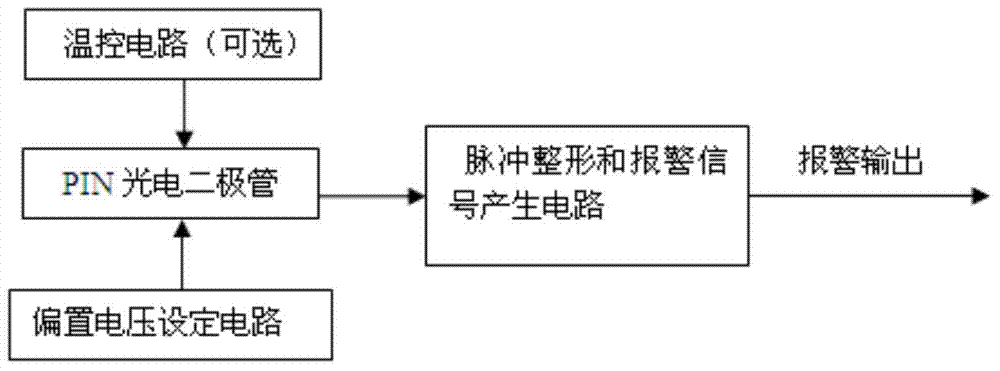
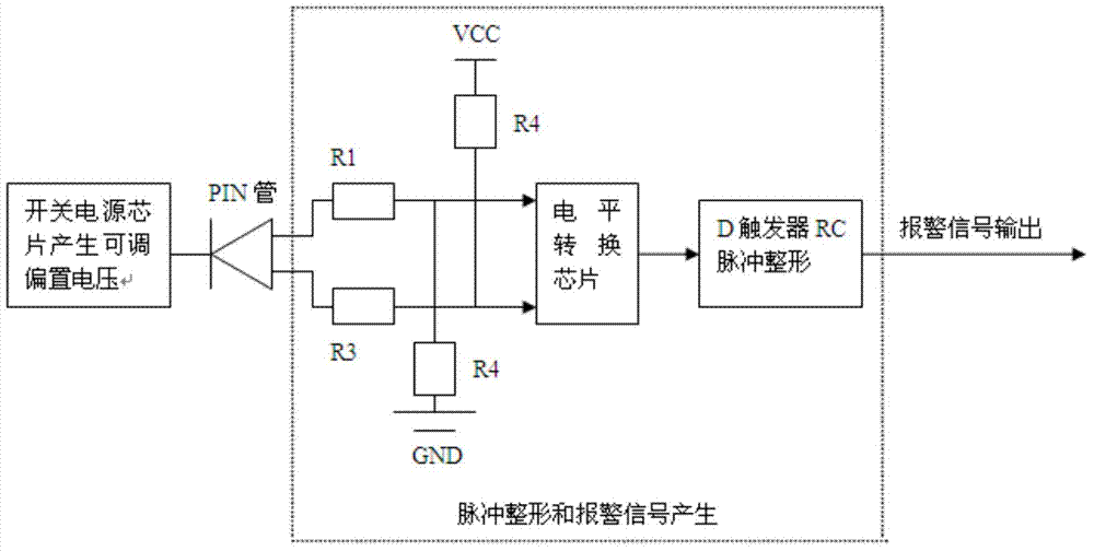
[0021] see figure 1 and figure 2 , the single photon detector strong light blinding monitoring device includes a temperature control circuit module, a PIN photodiode, a bias voltage setting module and a pulse shaping and alarm signal generation module; the bias voltage setting module and the PIN photodiode Electrically connected, the PIN photodiode is electrically connected to the pulse shaping and alarm signal generating module; the temperature control circuit module is used to heat or cool the PIN photodiode, and the PIN photodiode is used to convert the strong light narrow pulse signal sent by the attacker Generate a narrow pulse current, and output a narrow pulse voltage proportional to the narrow pulse current; the pulse shaping and alarm signal circuit is used to convert the narrow pulse voltage output by the PIN photodiode into a standard level that can be recognized by the subsequent main control chip ; The bias voltage setting module is used to set the reverse bias ...

Embodiment 2

[0028] see figure 1 , the single photon detector strong light blinding monitoring method comprises the following steps:

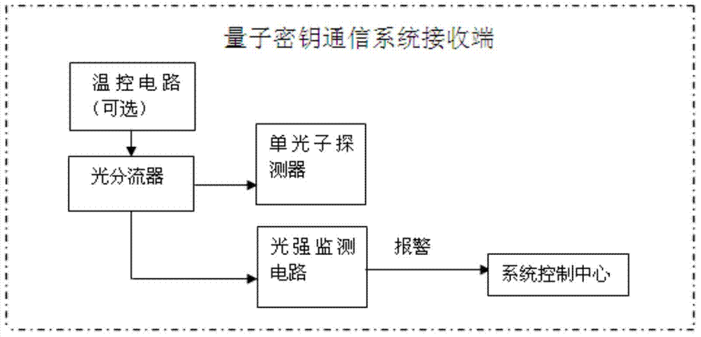
[0029] Optical splitting: introduce an optical splitter at the receiving end of the quantum key communication system to branch the quantum signal into two branches, one of which is sent to the single photon detector, and the other branch is sent to the single photon detector. Blinding monitoring device; the single-photon detector strong light blinding monitoring device is the same as in Embodiment 1, and will not be described in detail.

[0030] Strong light detection: through single photon detector strong light blinding monitoring device for strong light blinding monitoring;

[0031] Alarm: if the single photon detector strong light blinding monitoring device detects a strong light attack signal, it will send an alarm signal to the system control center.


PUM


Abstract

The invention discloses a hard light induced blindness monitoring device of a single-photon detector. The hard light induced blindness monitoring device comprises a temperature control circuit module, a PIN photoelectric diode, a bias voltage setting module and a pulse shaping and alarm signal generating module, wherein the PIN photoelectric diode is used for converting hard light narrow-pulse signals transmitted by an attacker into narrow-pulse current and outputting narrow-pulse voltage in proportion to the narrow-pulse current, the pulse shaping and alarm signal generating module is used for converting the narrow-pulse voltage outputted by the PIN photoelectric diode into a standard level which can be identified by follow-up master control chips, and the bias voltage setting module is used for setting reverse bias voltage added on the PIN photoelectric diode. The invention further discloses a hard light induced blindness monitoring method. The hard light induced blindness monitoring device is simple in circuit and low in cost, when showing up in quantum channels, hard light attack signals can be immediately monitored, and alarm signals can be transmitted to an upper computer, accordingly, absolute safety of a quantum key communication system is ensured.

Description

[0001] technical field [0002] The invention relates to a monitoring device and method for "strong light blinding" attacks in a quantum key distribution system, in particular to a single photon detector strong light blinding monitoring device and method. Background technique [0003] Quantum key distribution system (QKD) uses the basic principles of quantum mechanics to generate and distribute keys to ensure the absolute security of distribution. One of the reasons why quantum distribution can achieve absolutely safe distribution between the two parties is that a single photon is used to carry information. If an eavesdropper wants to obtain information, he must intercept the single photon that carries the information. Then Bob Ding did not receive this photon. Therefore, Alice will be notified to discard the information of the photon. According to the principle of wave-particle duality in physics, a single photon can only collapse to a point when it is measured, and cannot...

Claims


Application Information

Patent Timeline
IPC IPC(8): G01J1/42H04L9/08
Inventor 蒋金凤苗春华刘云赵义博韩正甫
Owner ANHUI QASKY QUANTUM SCI & TECH CO LTD
Why Eureka
Try Eureka