Braking system of vehicle and control method thereof, vehicle

A brake system and vehicle technology, applied in the direction of brakes, vehicle components, brake transmissions, etc., can solve the problems of high cost of remodeling, complicated control methods, and complicated remodeling

Active Publication Date: 2017-04-05
GREAT WALL MOTOR CO LTD
View PDF5 Cites 0 Cited by
  • Summary
  • Abstract
  • Description
  • Claims
  • Application Information

AI Technical Summary

Problems solved by technology

[0003] When researching and developing the braking system of hybrid electric vehicles, it is mainly based on the existing braking system of fuel vehicles. Type II, lengthening the brake master cylinder to recover braking energy, adding hydraulic oil return passages in the hydraulic module, and adding return passages to the brake fluid storage pot, etc. These modification methods require a lot of work and do not make the electric system Braking, hydraulic braking, and brake pedal operations form an associated closed-loop control, which has low braking energy recovery efficiency and affects driving comfort
Another type of restructuring method is to change the brake ABS control unit, add a return electromagnetic hydraulic valve on the basis of the original ABS control unit, and increase the control algorithm of electric braking and hydraulic braking. This kind of restructuring is complicated and needs to upgrade the original ABS. system, and the control method after restructuring is also complicated, and the cost of restructuring is high

Method used


Image

  • Braking system of vehicle and control method thereof, vehicle
  • Braking system of vehicle and control method thereof, vehicle
  • Braking system of vehicle and control method thereof, vehicle

Examples


Embodiment Construction

[0045] Specific embodiments of the present invention will be described in detail below in conjunction with the accompanying drawings. It should be understood that the specific embodiments described here are only used to illustrate and explain the present invention, and are not intended to limit the present invention.

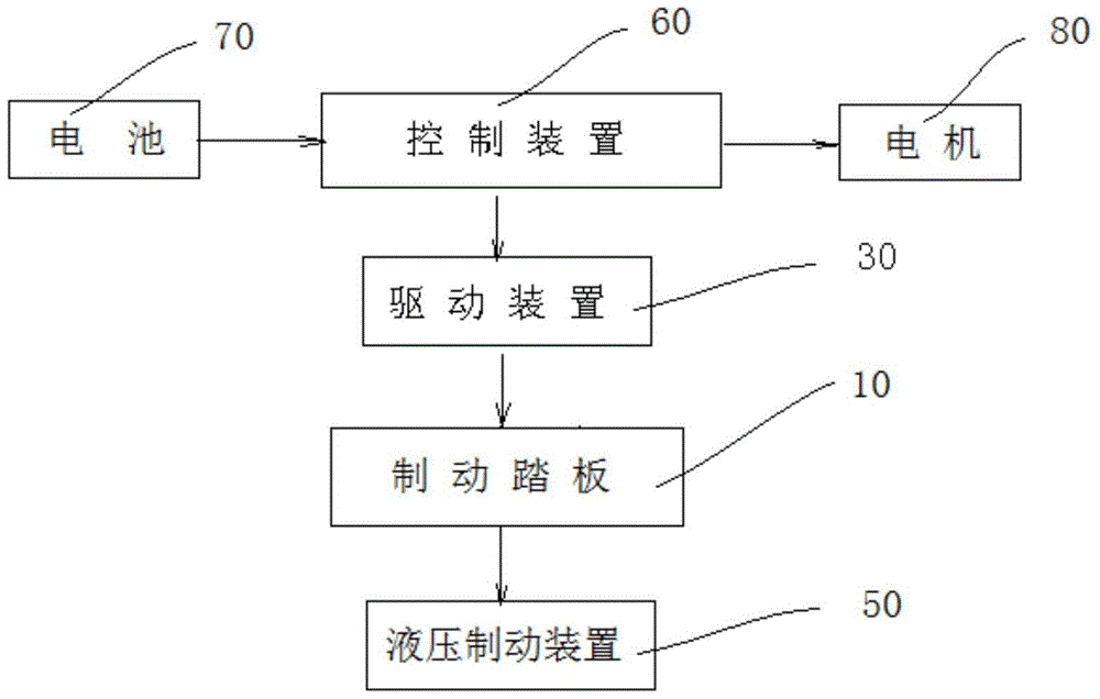
[0046] see figure 1 , The brake system of the present invention includes a control device 60 , a drive device 30 , a brake pedal 10 , a hydraulic brake device 50 and a motor 80 . The control device 60 receives the charge state information of the battery 70 of the vehicle, and sends a control signal to the drive device 30 according to the information, so that the drive device 30 drives the brake pedal 10 to rotate to a preset position; the control device 60 also Send a control signal to the motor 80 according to the information that the brake pedal 10 is stepped on, so that the motor 80 works as a generator to generate braking force and charge the battery 70 . ...


PUM


Abstract

The invention discloses a vehicle brake system, a control method of the vehicle brake system and a vehicle. The brake system comprises a brake pedal; a driving device for driving the brake pedal; a hydraulic brake device with a pushrod, wherein the pushrod is provided with a sliding groove, the brake pedal is slidably connected with the pushrod and the brake pedal can slide between a first limit position and a second limit position of the sliding groove; a control device and a motor, wherein the control device controls the brake pedal to rotate to a preset position; when the brake pedal is stepped down, the control device outputs a control signal to enable the motor to brake and charge a battery; when the brake pedal is stepped down and continuously rotates after the brake pedal rotates to the second limit position, the pushrod is pushed to realize braking through a brake master cylinder. The vehicle brake system disclosed by the invention has the advantages that the associated control between the stepping of the brake pedal and electric braking and hydraulic braking is realized through a mechanical structure, and the control method is simple and stable.

Description

technical field [0001] The present invention relates to a braking system of a vehicle and a control method for the braking system, in particular, to a braking system for a hybrid vehicle and a control method for the braking system. Background technique [0002] Hybrid vehicles usually use a combination of electric drive and fuel drive, which is an important direction for the development of energy-saving and environment-friendly vehicles. When the hybrid vehicle is coasting and braking, it can use the reverse operation of the motor to generate electricity and store the electric energy in the power battery, so as to make full use of the kinetic energy of the vehicle and achieve the purpose of improving energy utilization efficiency. [0003] When researching and developing the braking system of hybrid electric vehicles, it is mainly based on the existing braking system of fuel vehicles. Type II, lengthening the brake master cylinder to recover braking energy, adding hydraulic...

Claims


Application Information

Patent Timeline
Patent Type & Authority Patents(China)
IPC IPC(8): B60T13/66B60W10/18B60W10/26B60W40/00
Inventor 魏文彬吴世超候海杰王硕翁浩宇尹彩锋
Owner GREAT WALL MOTOR CO LTD
Why Eureka
Try Eureka