High-reliability landing gear control system

A control system and landing gear technology, applied in the chassis and other directions, can solve the problems of large fluctuations in braking efficiency, poor adaptability of runways and braking materials, etc.

Active Publication Date: 2014-12-24
CHINA ACAD OF LAUNCH VEHICLE TECH
View PDF4 Cites 26 Cited by
  • Summary
  • Abstract
  • Description
  • Claims
  • Application Information

AI Technical Summary

Problems solved by technology

In the past, the wheel anti-skid brake, front wheel steering control, and landing gear retraction control were set independently. During the anti-skid brake process, the influence of aircraft tire pressure,

Method used


Image

  • High-reliability landing gear control system
  • High-reliability landing gear control system
  • High-reliability landing gear control system

Examples


Embodiment Construction

[0043] Below in conjunction with accompanying drawing and specific embodiment the present invention is described in further detail:

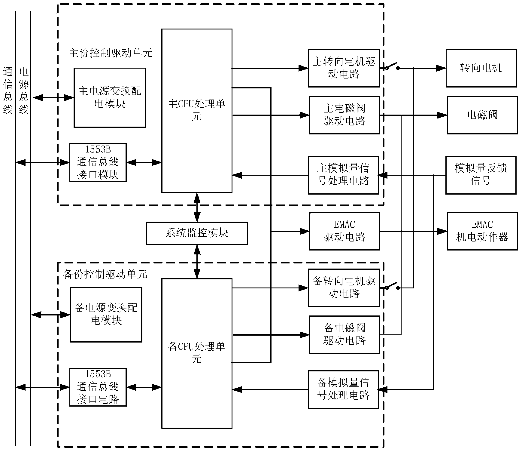
[0044] Such as figure 1 Shown is a composition block diagram of the landing gear control system of the present invention. The control system of the present invention is a dual-redundancy design, including a primary control drive unit, a backup control drive unit, a system monitoring module and an EMAC drive circuit.

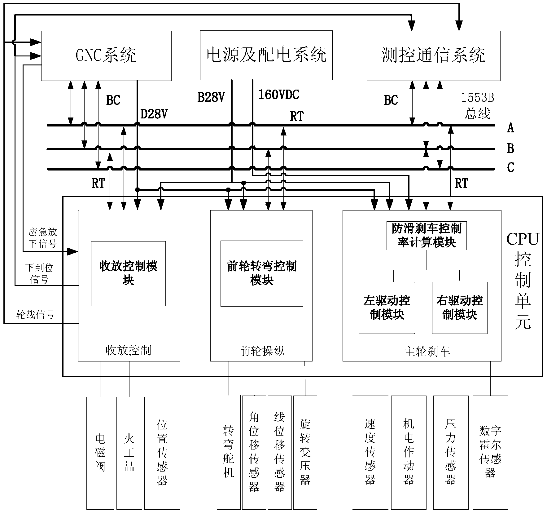
[0045] The main control drive unit includes the main power conversion and distribution module, the 1553B bus interface module, the main CPU processing unit, the main steering motor drive circuit, the main solenoid valve drive circuit and the main analog signal processing circuit. The main CPU processing unit includes the receiver control module, front wheel steering control module and anti-skid brake driving control module, the functions of each module are as follows:

[0046] The main power conversion and distribution module conv...


PUM


Abstract

The invention relates to a high-reliability landing gear control system. The high-reliability landing gear control system comprises a control driving unit and an EMAC driving circuit, wherein the control driving circuit comprises a power supply transformation power distribution module, a 1553B bus interface module, a CPU processing unit, a steering motor driving circuit, a solenoid valve driving circuit and an analog quantity signal processing circuit, wherein the CPU processing unit comprises a taking-up and releasing control module, a front wheel steering control module and an anti-skid braking driving control module; the landing gear control system adopts a driving and control integrated design, the CPU processing unit can be used for achieving combined control on taking up and releasing of a landing gear and a cabin door, the steering of a front wheel, and the anti-skid braking of an electro-mechanical actuator of a main engine wheel, and the system is light in weight, low in power consumption, high in reliability and good in environment adaptation, and can be widely applied to novel spacecraft landing recovery systems and traditional aircraft landing gear systems.

Description

technical field [0001] The invention relates to a high-reliability landing gear control system, which is suitable for the application field of a new spacecraft landing recovery system. Background technique [0002] The landing gear system is a subsystem with relatively independent functions on the aircraft. Its function is to bear the static weight and dynamic impact load of the aircraft and absorb the kinetic energy of the aircraft when it lands, so as to realize the braking and control of the aircraft's take-off, landing, taxiing, and turning. Its performance directly affects the aircraft's rapid response, safe return and launch, and continuous combat capability, which in turn affects the overall performance of the aircraft. [0003] The impact of the space environment has never been considered in the design of conventional landing gear. They are all designed for aircraft within the atmosphere and cannot adapt to space environments such as high vacuum, large temperature di...

Claims


Application Information

Patent Timeline
IPC IPC(8): B64C25/24B64C25/26
Inventor 张庆利姚世东张涛王悦孔文秦王涛徐方舟石小亮彭波贾磊穆星科张晓帆李永俊陈飞
Owner CHINA ACAD OF LAUNCH VEHICLE TECH
Why Eureka
Try Eureka