Oil well fault diagnosis method based on neural network

A neural network and fault diagnosis technology, which is applied in construction and other fields, can solve problems such as misjudgment of pumping well conditions, incomplete knowledge, and insufficient practical experience, so as to improve the accuracy rate, overcome the inconsistency of manual interpretation standards, and achieve better results. adaptive effect

Inactive Publication Date: 2014-12-24
RES INST OF SHAANXI YANCHANG PETROLEUM GRP
View PDF4 Cites 11 Cited by
  • Summary
  • Abstract
  • Description
  • Claims
  • Application Information

AI Technical Summary

Problems solved by technology

Manual interpretation is greatly restricted by the experience and technical level of technicians, and the interpretation results vary from person to person. Moreover, the number of interpretations that can be interpreted every day is extremely limited by using manual interpretation of the dynamometer diagram. The problems existing in the oil well cannot be detected in time, often resulting in relatively large The loss of the oil field can no longer meet the needs of normal production in the oil field; the fault diagnosis expert system that has been put into use, because its establishment is often restricted by knowledge and information acquisition, can only deal with symbolic reasoning in a single field of knowledge. When a fault occurs, if the system knowledge is not comprehensive and the practical experience is not sufficient, then it is likely that only a superficial analysis of the fault or no effective and correct judgment can be made at all; in the current fault diagnosis of the dynamometer diagram, some pattern recognition is also introduced method, its main idea is to judge the fault type according to the graphic features of the dynamometer diagram, but this method has the disadvantage that it cannot accurately distinguish the small differences between the graphics, for example, the geometric features of the dynamometer diagrams of some faults are almost the same, at this time This method is difficult to make an accurate judgment and often leads to misjudgment of the working conditions of the pumping well

Method used


Image

  • Oil well fault diagnosis method based on neural network
  • Oil well fault diagnosis method based on neural network
  • Oil well fault diagnosis method based on neural network

Examples


Embodiment Construction

[0050] A neural network-based fault diagnosis method for pumping wells uses the following steps.

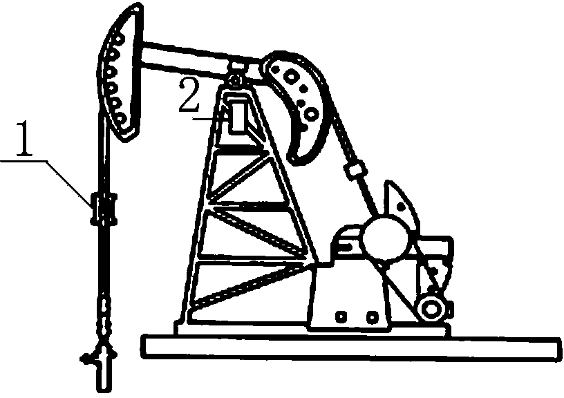
[0051] Step 1: Obtain the indicator diagram displacement and load data through the load and displacement sensor 1, and upload the above data to the database through the remote RTU cabinet 2.

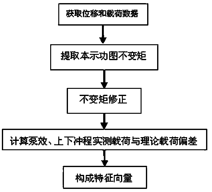
[0052] Step 2: Perform the following processing on the information in the aforementioned database to obtain a feature vector.

[0053] (1) Extract and normalize the central moment of the displacement and load data of the indicator diagram:

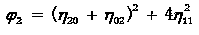
[0054] For an edge graphic composed of numbers, it is assumed that the edge curve is Discrete points consist of (x i , Y i ), i=1,2,...N; its p+q moment m pq Will be defined as:

[0055] ;

[0056] Where Represents the abscissa (displacement); Represents the ordinate (load); Represents the first edge of the curve Discrete points Is the number of discrete points; Is the straight line distance between adjacent points; its expression is ;

[0057] Therefor...


PUM


Abstract

The invention relates to a method for performing diagnosis on the working condition of a rod pumped well upon a neural network. An oil well fault diagnosis method based on the neural network comprises the following steps: S1, acquiring indicator diagram displacement and load data through a load and displacement sensor, and uploading the data to a database through a remote RTU (remote terminal unit) polished rod module; S2, performing the following processing shown in the specification on information in the database to obtain a feature vector; S3, establishing the radial basis function neural network to perform judgment. According to the method disclosed by the invention, blindness and nondeterminacy caused by simply depending on the graph geometrical characteristic are overcome; the diagnosis accuracy can be improved, and the production practice requirement is met.

Description

Technical field [0001] The invention relates to a method for diagnosing working conditions of a pumping well based on a neural network. Background technique [0002] At present, rod pumping technology is widely used in the country, and rod pumping wells account for the vast majority of oil wells in my country. Therefore, in production, timely identification of rod pumping system failures and appropriate measures to eliminate them will reduce production units Cost and improving efficiency are of great significance. System working condition analysis through the indicator diagram of pumping unit well is the main method of current oil well working condition diagnosis. [0003] At present, the method of interpreting the indicator diagram can be attributed to the manual discrimination method, the fault diagnosis expert system of the rod pump and the pattern recognition system. Manual interpretation is greatly restricted by the experience and technical level of technicians. The interpret...

Claims


Application Information

Patent Timeline
Patent Type & Authority Applications(China)
IPC IPC(8): E21B47/008
Inventor 王香增冯博陶红胜赵亚杰申峰高庆华
Owner RES INST OF SHAANXI YANCHANG PETROLEUM GRP
Why Eureka
Try Eureka