Supercharge Your Innovation With Domain-Expert AI Agents!

Middle through hole dynamic throttling element flowmeter

A throttling element and flowmeter technology, which is applied in the direction of detecting fluid flow by measuring pressure difference, volume/mass flow generated by mechanical effects, etc., can solve difficulties, bellows are difficult to implement, and affect the promotion of dynamic throttling element flowmeters, etc. problem, to achieve the effect of low price, high adaptability and reliability, and simple structure

Active Publication Date: 2018-12-07
海宁市洛溪实业发展有限公司
View PDF7 Cites 0 Cited by
  • Summary
  • Abstract
  • Description
  • Claims
  • Application Information

AI Technical Summary

Problems solved by technology

However, in the "flowmeter with elastic diaphragm or bellows connected to the dynamic throttling element in the middle part", it is a relatively difficult process to connect a bellows at both ends of the dynamic throttling element, because the thin-walled There is a problem in the interconnection between the metal bellows and the dynamic throttling element. Whether it is threaded or welded, it is difficult to implement because the wall of the bellows is thin, which affects the promotion of this dynamic throttling element flowmeter.

Method used


Image

  • Middle through hole dynamic throttling element flowmeter
  • Middle through hole dynamic throttling element flowmeter
  • Middle through hole dynamic throttling element flowmeter

Examples


Embodiment 1

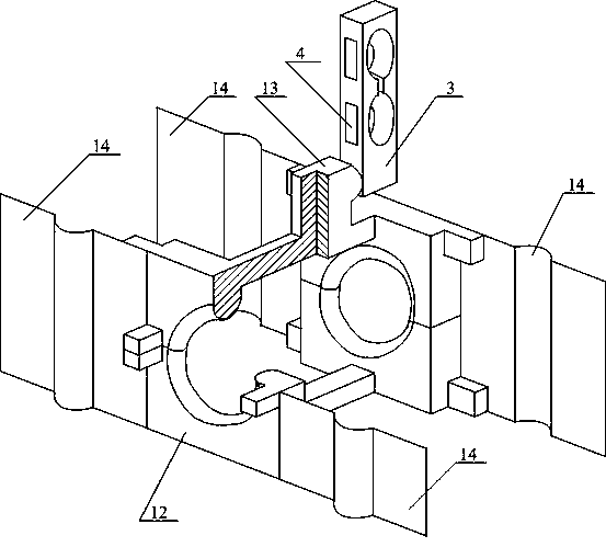
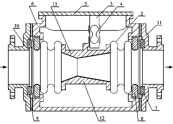
[0014] exist figure 1 In the embodiment, the moving Venturi tube 1 is placed in the middle of the inner cavity of a corrugated tube 2, the outer diameter of the two ends of the moving Venturi tube 1 is slightly smaller than the outer diameter of the middle part, and the two ends of the upper fixed tile 13 and the lower fixed tile 12 are convex. The inner surface of the edge has a shape that matches the trough of the outer surface of the corrugated pipe 2. Because the corrugated pipe is thin-walled, it is easy to produce slight deformation. Therefore, when the upper fixed tile 13 and the lower fixed tile 12 are locked together, the corrugated The inner flange of the fixed tile on the outside of the tube 2 can clamp the outer edges of both ends of the moving Venturi tube 1 with a slightly smaller diameter, so that the mutual positions of the waves between the moving Venturi tube 1 and the bellows 2 remain unchanged during the measurement process. From figure 2 It can be seen i...

Embodiment 2

[0046] exist image 3 In the implementation scheme, it can be seen that this example and figure 1 The embodiments are largely the same in structure, just not like figure 1 Instead of using a separately manufactured dynamic venturi tube 1 as in the above, a single bellows 2 in the shape of a special-shaped bellows is used, that is, the middle section of the bellows 2 is directly made into a venturi profile by means of electrodeposition, chemical deposition or welding. shape. Because the profile of the Venturi tube in the middle section of the bellows 2 is thin-walled, the inner surfaces of the upper fixed tile 13 and the lower fixed tile 12 are made into a shape that matches the profile of the Venturi tube to prevent the corrugated tube 2 from The venturi profile deforms under the internal pressure of the fluid being measured. The upper fixed tile 13 and the lower fixed tile 12 are also made of figure 2 The same supporting spring 14 bears weight, and is not drawn separatel...

Embodiment 3

[0048] exist Figure 4 In the implementation scheme, it can be seen that this example and image 3 The embodiments of the present invention are substantially the same in structure, except that the two ends of the bellows 2 are not fixed with the opening collar 8, but are directly fixed with the watch case 6 inlet pipe and the outlet pipe. For fixing needs, the shape of the two ends of the single bellows 2 matches the shape of the inlet pipe and the outlet pipe of the watch case 6 . Because the diameter of the fixed flange at both ends of the bellows 2 is greater than the diameter of the inlet pipe or the outlet pipe of the watch case 6, the watch case 6 is combined by two parts separated up and down for the mutual assembly of each component. When the flowmeter is connected with the outer connection pipe 15 of the case inlet, the outer connection pipe 16 of the case outlet and the sealing gasket 7, a measured fluid flows in from the outer connection pipe 15 of the case inlet, ...


PUM


Abstract

The invention discloses a novel central through hole dynamic throttling element flowmeter, which belongs to the throttling flowmeter in the technical field of automatic detection; Composed of a single bellows, a watch case, and a force sensor; the flowmeter has two structural types, one is to install a dynamic throttling element with a middle through hole in the middle of the single bellows inner cavity, and the other is to install a dynamic throttling element in the middle of the single bellows The shape of the middle through hole is made into the profile of the dynamic throttling element, and the middle through hole dynamic throttling element and its fixing accessories are supported by the elastic support reed; compared with the differential pressure flowmeter, the flowmeter can fully exert its In addition to the superior performance of the throttling device, it has the advantages of simpler structure, lower price, smaller resistance loss, longer service life, higher precision, anti-clogging, wider application range, etc., and has extremely broad development prospects.

Description

technical field [0001] The invention relates to an instrument for realizing flow detection in the technical field of automatic detection, in particular to a flow meter of a throttling element. Background technique [0002] In the field of flow measurement, the development of throttling devices has a long history. As early as the beginning of the 17th century, the research of Castelli and Torricelli laid the theoretical foundation for throttling devices. In the 1920s, the United States and some European countries began to conduct large-scale experimental research on throttling devices almost at the same time, resulting in the differential pressure flowmeter that is still widely used today. But it is a pity that these European and American scientists followed the previous research model of fixed throttling devices, so the differential pressure flowmeter they developed did not give full play to all the advantages that throttling devices should have. In fact, in 1855, only a d...

Claims


Application Information

Patent Timeline
Patent Type & Authority Patents(China)
IPC IPC(8): G01F1/36
Inventor 王可崇
Owner 海宁市洛溪实业发展有限公司
Features
  • R&D
  • Intellectual Property
  • Life Sciences
  • Materials
  • Tech Scout
  • Unparalleled Data Quality
  • Higher Quality Content
  • 60% Fewer Hallucinations
Learn More