
Dynamic system multi-physics field imaging detection system

A multi-physics, imaging detection technology, used in measuring devices, measuring ultrasonic/sonic/infrasonic waves, instruments, etc., can solve the problem of not reflecting the changes in physical quantities such as the temperature and material of the vibration source, and not being able to better detect high finish and complexity. Surface vibration, difficulty in realizing multi-spectral, high-precision vibration detection, etc., to achieve the effect of improving reliability and measurement accuracy, maintaining color purity, and improving synchronous sampling accuracy

Inactive Publication Date: 2014-12-24
HEFEI UNIV OF TECH
View PDF10 Cites 6 Cited by
  • Summary
  • Abstract
  • Description
  • Claims
  • Application Information

AI Technical Summary

Problems solved by technology

[0004] In the prior art, although the measurement method based on machine vision solves some of the above-mentioned problems, there are still many problems, such as: due to the deficiency of the general lighting system, the vibration of high-gloss and complex surfaces cannot be detected well, the detection accuracy and Low accuracy; lack of synchronous sampling device, which increases the error of subsequent information processing; ordinary high-speed camera is used for detection, the measurement physical quantity is single, and the measurement efficiency is low
Among them, the camera vibration detection device designed by patent No.200910170797.9 adopts the method of machine vision to detect vibration, but the camera it uses is not a multi-spectral camera, which cannot meet the requirements of high-quality images. The collected information only contains image information and cannot reflect Changes in physical quantities such as temperature and materials of the vibration source
It is difficult to realize multi-spectrum and high-precision vibration detection, which has great limitations

Method used


Image

  • Dynamic system multi-physics field imaging detection system
  • Dynamic system multi-physics field imaging detection system

Examples


Embodiment Construction

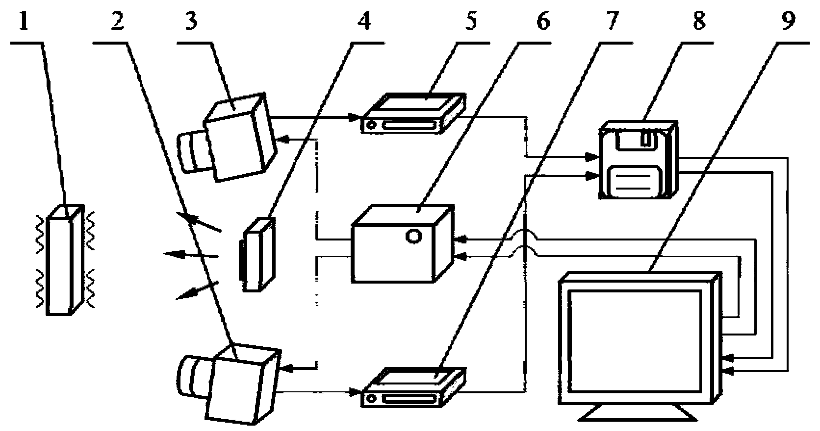
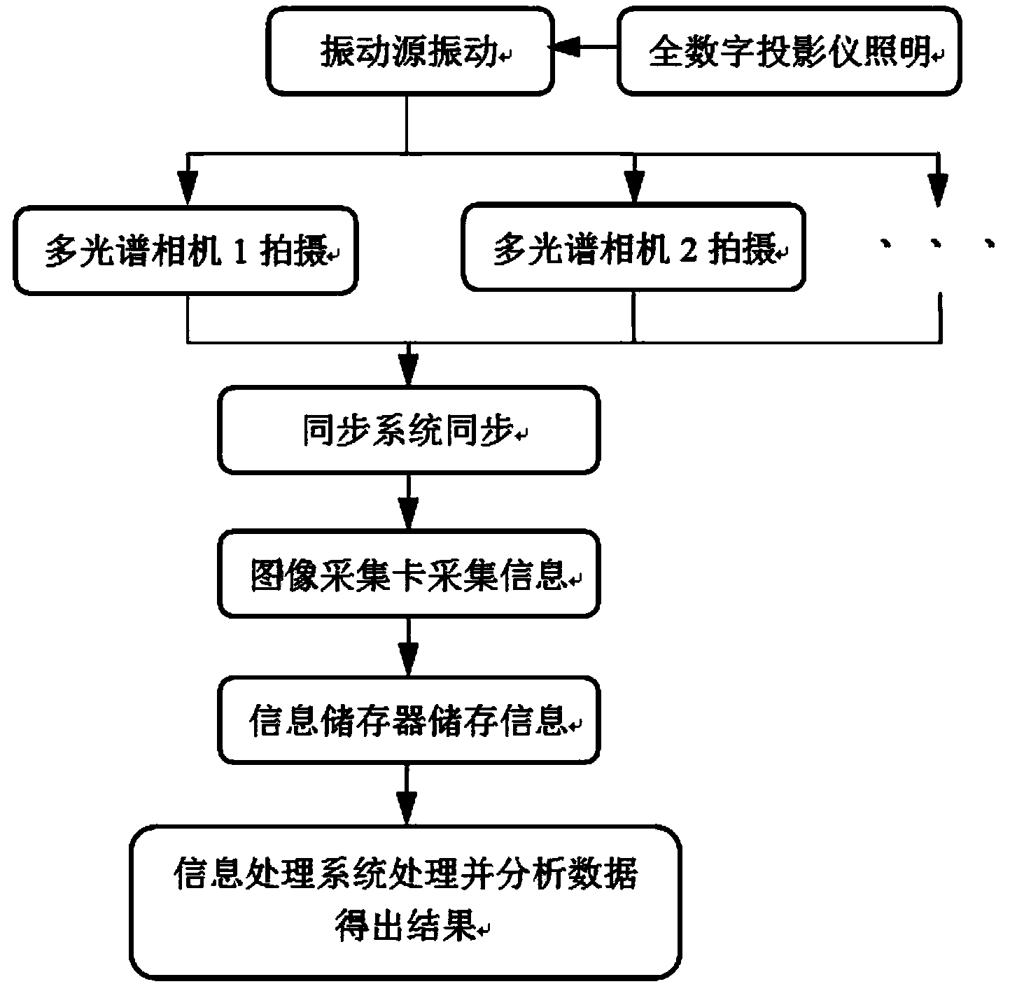
[0017] The present invention will be further described below in conjunction with the accompanying drawings and embodiments. Such as figure 1 , 2 As shown, two (multiple) multispectral cameras 2 and 3 are placed directly in front of the vibration source 1 and kept at an appropriate distance and height. According to technical requirements, a multispectral camera of the model Condor-1000 MS5 can be used, which uses The principle of prism splitting produces 5 separate beams corresponding to 5 CCD chips, corresponding to red, green, blue and two infrared images. It is required that the distance and height are adjustable according to the actual situation. The two multi-spectral cameras 2 and 3 can be fixed by two multi-degree-of-freedom tripods. The gimbal is fixed so that it can be used to adjust the angle of the two multispectral cameras 2 and 3. The two multispectral cameras 2 and 3 require synchronization when collecting data, which can be realized by a synchronous sampling d...


PUM


Abstract

The invention discloses a dynamic system multi-physics field imaging detection system which comprises a digital projection illuminating device. The digital projection illuminating device is arranged right in front of a measured vibration object, multi-spectral cameras are symmetrically arranged on the two sides of the digital projection illuminating device, and the surface of the measured vibration object radiates under the irradiation of the digital projection illuminating device. A synchronous sampling device controls the multi-spectral cameras to capture a radiance image of the measured vibration object at the same time, an image capture card is connected with the multi-spectral cameras to be used for collecting data and outputting the image data to an information storing device and an information processing system, the synchronous sampling device is connected to the information processing system, and the information processing system is a PC. According to the dynamic system multi-physics field imaging detection system, a digital projector is used for lighting, the synchronous sampling system is additionally arranged, so that measuring errors are reduced, and the measuring accuracy is improved; the wavelength measuring range is wide, a plurality of wavebands can be measured, the multiple physical quantities such as the vibration source temperature and the materials can be detected, and therefore the measuring reliability and the measuring precision are improved.

Description

technical field [0001] The invention relates to a vibration detection system, in particular to a dynamic system multi-physical field imaging detection system. Background technique [0002] Around us, vibration exists all the time. Vibrations generated by cars and trains; vibrations generated by tsunamis and earthquakes; vibrations of the internal structure of flying space shuttles, etc. All are closely related to our human life and work, so how to accurately and quickly detect adverse vibrations and correctly analyze the results is very important. [0003] At present, people have invented many ways to measure vibration, such as traditional contact and laser-based non-contact vibration testing methods, but these methods are difficult to achieve multi-spectral, high-precision vibration testing. Among them, the contact vibration test method needs to attach or paste sensors (such as accelerometers, etc.) to the surface of the measured object, and it is difficult to detect some...

Claims


Application Information

Patent Timeline
IPC IPC(8): G01H9/00
Inventor 张进邓华夏梁超佳于连栋
Owner HEFEI UNIV OF TECH
Learn More