Motor rotor cooling structure

A technology for cooling structure and motor rotor, applied in the direction of magnetic circuit shape/style/structure, magnetic circuit rotating parts, etc., can solve the problem of poor cooling effect of motor rotor, improve heat conduction efficiency, improve cooling effect, and reduce machining accuracy desired effect

Active Publication Date: 2014-12-24
于贻鹏
View PDF6 Cites 4 Cited by
  • Summary
  • Abstract
  • Description
  • Claims
  • Application Information

AI Technical Summary

Problems solved by technology

[0005] The invention aims to solve the problem that the working medium cannot quickly return to the heat-absorbing end when cooling the motor rotor with a heat-conducting tube, and the cooling effect of the motor rotor is poor. It provides a cooling structure for the motor rotor using a heat-conducting tube, which can effectively avoid Influence of Rotor High-speed Rotation on Cooling Efficiency of Heat Transfer Tube

Method used


Image

  • Motor rotor cooling structure
  • Motor rotor cooling structure
  • Motor rotor cooling structure

Examples


Embodiment Construction

[0024] The present invention will be further described below in conjunction with the accompanying drawings and specific embodiments.

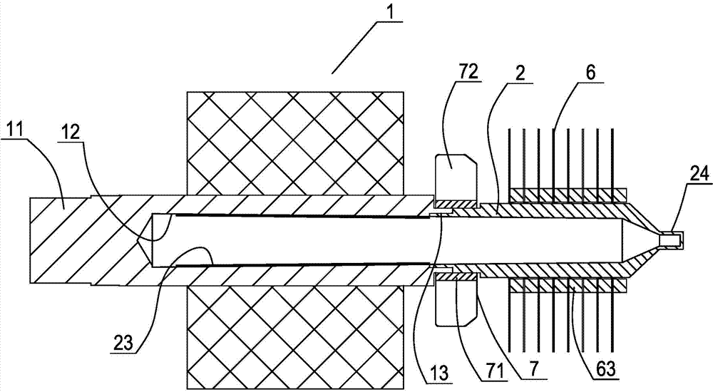
[0025] Such as figure 1 As shown, a motor rotor cooling structure is used to cool the motor rotor, including a rotor 1 and a heat pipe 2, and the motor shaft 11 used for output torque on the rotor is provided with a coaxial blind hole at one end in the motor housing 12. One end of the heat pipe is provided with a seal 24 for packaging, while the other end is open, and the open end of the heat pipe is fixedly connected to the open end of the blind hole. In this way, the motor shaft becomes an extension of the heat pipe, thus forming a spliced ​​heat pipe. Of course, it is understandable that after fixing the heat pipe to the motor shaft, we need to pour the corresponding working medium into the heat pipe, and then use The seal seals the heat pipe. Since the heat pipe has a high heat transfer rate, the heat generated by the rotor during operati...


PUM


Abstract

The invention discloses a motor rotor cooling structure. The motor rotor cooling structure comprises a rotor and a heat conducting pipe, a seal is arranged at one end of the heat conducting pipe, the other end of the heat conducting pipe is open, the end, located in a motor casing, of a motor shaft on the rotor is provided with a coaxial blind hole, the open end of the heat conducting pipe is fixedly connected to the open end of the blind hole, the inner diameter of the heat conducting pipe gradually increases from the end with the seal to the open end, and a sintered layer is arranged on the inner wall of the blind hole of the motor shaft. According to the motor rotor cooling structure, the influence on the cooling efficiency of the heat conducting pipe caused by high-speed rotation of the rotor can be effectively avoided so that a motor can have a reliable cooling effect, and meanwhile the motor can be conveniently manufactured.

Description

technical field [0001] The invention relates to the field of motor technology, in particular to a motor rotor cooling structure. [0002] Background technique [0003] The motor will generate heat when it is working, and it usually dissipates heat through the casing, or installs blades on the rotor to suck the air outside the casing into the casing, and then achieve the purpose of cooling. However, the above cooling methods have low cooling efficiency, and Noise problem. With the advancement of technology, people realize the cooling of the motor by arranging heat pipes that can conduct heat quickly on the motor. For example, a "motor cooled by heat pipe cooling method" disclosed in Chinese patent literature, the publication number is CN102751803A, the motor uses heat pipes to directly transfer the heat emitted by the motor heat source to cool the motor, including the stator and rotor , armature winding and two sets of independent heat pipe cooling groups, which can be use...

Claims


Application Information

Patent Timeline
Patent Type & Authority Applications(China)
IPC IPC(8): H02K1/32
Inventor 於贻鹏陈肃蓓
Owner 于贻鹏
Why Eureka
Try Eureka