Novel method for rapidly diagnosing plasma in real time through quasi-optical resonant cavity

A technology of optical resonant cavity and plasma, which is applied in the field of optical resonant cavity, can solve the problems that the measurement accuracy and measurement range cannot meet the requirements, and achieve the effect of rapid data measurement and extraction

Inactive Publication Date: 2014-12-24
UNIV OF ELECTRONIC SCI & TECH OF CHINA
View PDF8 Cites 5 Cited by
  • Summary
  • Abstract
  • Description
  • Claims
  • Application Information

AI Technical Summary

Problems solved by technology

Microwave interferometer diagnostic technology is a method that can quickly measure plasma in real time, but the measurement accuracy and measurement range of this method often cannot meet the requirements

Method used


Image

  • Novel method for rapidly diagnosing plasma in real time through quasi-optical resonant cavity
  • Novel method for rapidly diagnosing plasma in real time through quasi-optical resonant cavity
  • Novel method for rapidly diagnosing plasma in real time through quasi-optical resonant cavity

Examples


Embodiment Construction

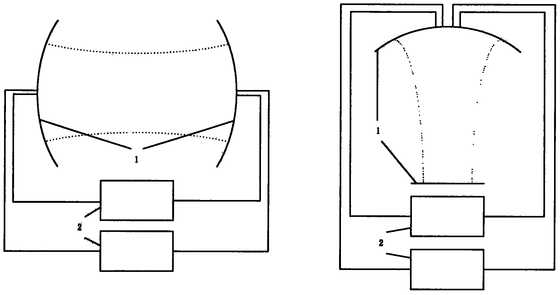
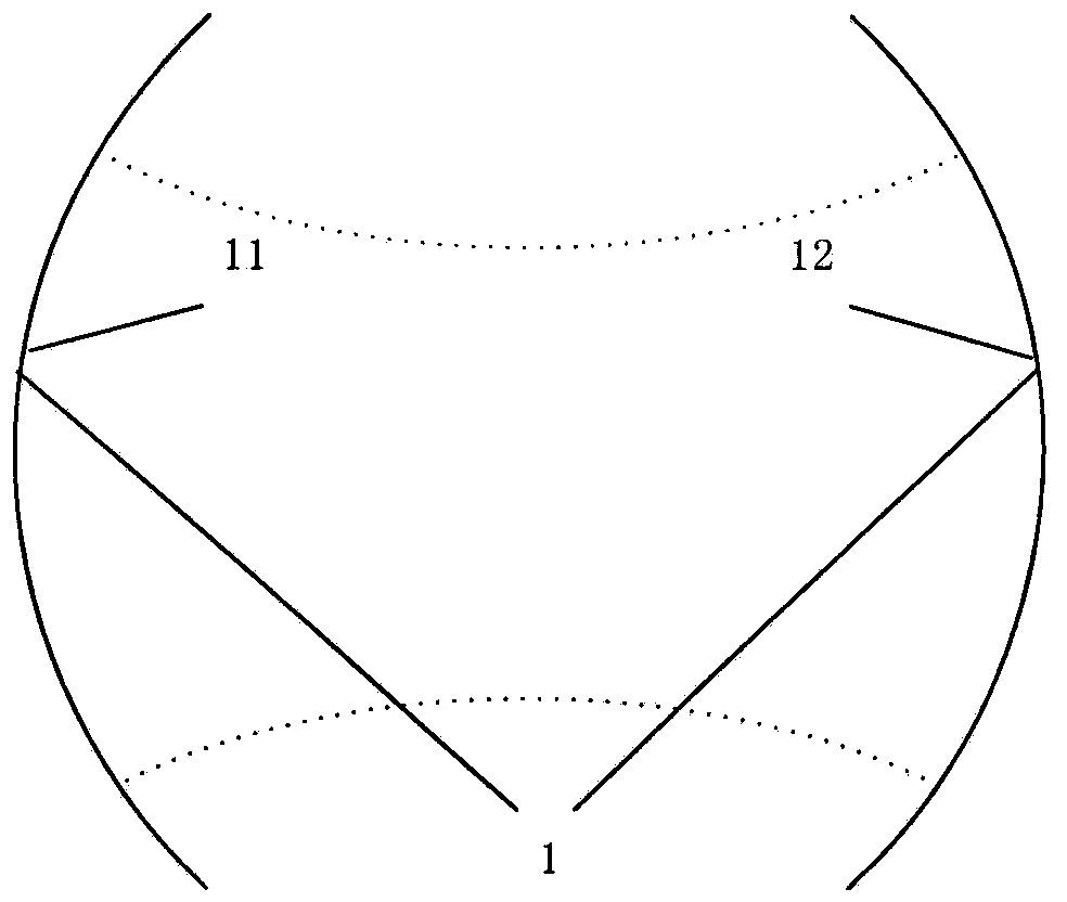
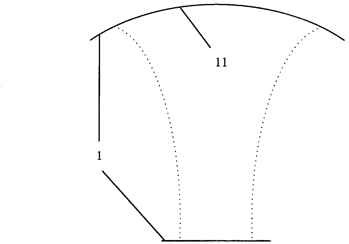
[0012] A new method for rapid real-time diagnosis of plasmas using quasi-optical resonant cavities, devices such as figure 1 As shown, it includes a quasi-optical resonator 1 and a vector network analyzer 2 . The quasi-optical resonant cavity 1 can be a symmetrical double concave cavity or a flat concave cavity. For the device in which the quasi-optical resonant cavity is a symmetrical double concave cavity, the test signal generated by the first vector network analyzer is transmitted through a section of coaxial line, and passes through the input coupling hole 111 located in the center of the concave mirror 11 in the symmetrical double concave cavity Then coupled into the symmetrical double concave cavity; after the signal passes through the symmetrical double concave cavity, it is coupled into another section of coaxial line through the output coupling hole 121 in the center of the concave mirror 12 in the symmetrical double concave cavity and then transmitted back to the ve...


PUM


Abstract

The invention provides a novel method for rapidly diagnosing plasma in real time through a quasi-optical resonant cavity and belongs to the field of plasma diagnosis. A diagnosis device comprises the quasi-optical resonant cavity and vector network analyzers, wherein the quasi-optical resonant cavity is a symmetric biconcave cavity or a flat concave cavity. Test signals enter the resonant cavity through a coaxial line and a coupling input hole; after penetrating through the resonant cavity, the signals are transmitted back to the vector network analyzers through a coupling output hole and a coaxial line. The two or more vector network analyzers are used for selecting different frequencies to conduct dot frequency tests (CW Sweep) and parameters of the plasma are calculated according to measuring results. The novel method is suitable for diagnosing plasma of a flight back trace type and has the advantages of being rapid, accurate and wide in measuring range.

Description

technical field [0001] The invention belongs to the field of plasma diagnosis and relates to a quasi-optical resonant cavity for testing complex dielectric constants of dielectric materials in microwave and millimeter wave frequency bands. Background technique [0002] Plasma microwave diagnostic methods mainly include electrostatic probe method and microwave diagnostic method. The electrostatic probe method is often used in the diagnosis of low-temperature plasma, and the microwave diagnostic method is often used in the diagnosis of high-temperature plasma. Microwave diagnostic methods are further divided into microwave probe diagnostic methods, microwave cavity diagnostic methods, and plasma radiation diagnostic methods. The open-cavity diagnosis method in the microwave cavity diagnosis method is often used in plasma diagnosis in the millimeter wave frequency band. [0003] Quasi-optical resonant cavity, referred to as quasi-optical cavity. There are two commonly used q...

Claims


Application Information

Patent Timeline
IPC IPC(8): H05H1/00
Inventor 陶冰洁谢冰郭高凤李恩高源慈郑虎
Owner UNIV OF ELECTRONIC SCI & TECH OF CHINA
Why Eureka
Try Eureka