
Drive unit with oil exchange

A drive unit, oil chamber technology, applied in the direction of electric components, electrical components, transmission parts, etc., can solve the problem of not giving

Active Publication Date: 2014-12-24
BOMBARDIER TRANSPORTATION GMBH
View PDF7 Cites 10 Cited by
  • Summary
  • Abstract
  • Description
  • Claims
  • Application Information

AI Technical Summary

Problems solved by technology

The solution presented in this document does not however give a solution to the problem of how to feed the lubricating medium to the bearing points of the differential

Method used


Image

  • Drive unit with oil exchange

Examples


Embodiment Construction

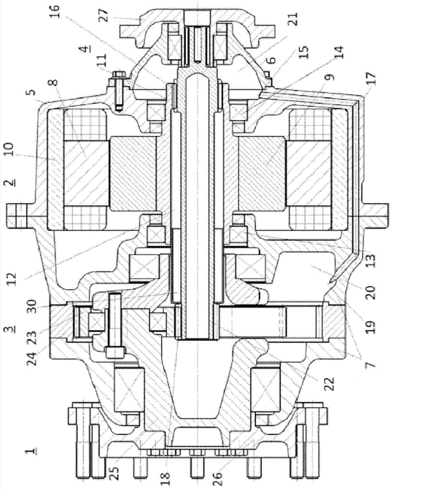
[0015] exist figure 1 shows a drive unit 1 according to the invention, which comprises an electric motor 2 and a transmission 3 as well as a brake 4 . All individual components of drive unit 1 are combined in a housing. Here, the housing of the electric machine 2 is designated with 5 , the bearing cover of the brake is designated with 6 and the housing of the transmission is designated with 7 . The housing parts 5 , 6 , 7 are connected to one another in a sealed manner and can also be constructed in multiple parts. The housing of the transmission 7 is thus constructed in two parts in this figure. The electric machine 2 shown schematically has a stator 8 and a rotor 9 . The rotor 9 is fixedly connected to a hollow shaft 11 and is mounted rotatably in the housing parts 6 and 7 by means of bearings 13 and 14 . The electric machine 2 has a cooling shell 10 . The cooling of the electric machine 2 takes place separately from the lubrication circuit. Said electric machine 3 is ...


PUM


Abstract

The invention relates to a drive unit with oil exchange for vehicles, which drive unit has a gearbox (3), a brake (4) and an electric machine (2), arranged between the latter, in an at least two-part housing (5, 6, 7), wherein the electric machine (2) has a cooling jacket (10), and the further components (3, 4) are lubricated via a separate lubricant circuit. According to the invention there is provision that the separate lubricant circuit in the at least two-part housing (5, 6, 7) for the gearbox (3) and brake (4) is maintained by using existing components (23, 22, 11).

Description

technical field [0001] The invention relates to a drive unit for a vehicle comprising a transmission, a brake and an electric machine arranged between the transmission and the brake. The electric machine has a cooling device which acts separately from the other components. In these other components, a separate lubrication circuit is maintained while using the existing components and is used as a further cooling circuit. Background technique [0002] Document DE69923553 T2 is known from the prior art. This document describes a drive unit having a liquid-cooled electric motor with a connected planetary transmission. The drive is provided with a water cooling for the electric motor, wherein the cooling circuit is driven by the pump function in the planetary transmission. For this purpose, the connected planetary transmission must be suitably constructed and the components must be specially preformed. In the prior art, the ring gear of the planetary transmission is shaped su...

Claims


Application Information

Patent Timeline
Patent Type & Authority Applications(China)
IPC IPC(8): F16H57/04H02K1/32H02K5/20H02K7/116
CPCF16H57/0445F16H57/0471F16H57/0476H02K1/32H02K7/083H02K7/116H02K7/102H02K9/227F16H57/0457H02K5/203
Inventor T·贡珀尔德斯贝格尔H·西格尔
Owner BOMBARDIER TRANSPORTATION GMBH
Learn More