FRP (Fiber Reinforced Plastic) bar and fiber high-strength concrete beam component

A technology of high-strength concrete and beam components, applied in the direction of joists, girders, truss beams, etc., can solve the problems of compressing available space, increasing deflection, and reducing stiffness, so as to increase available space, reduce cross-sectional size, The effect of improving durability

Inactive Publication Date: 2014-12-31
ZHENGZHOU UNIV
View PDF5 Cites 15 Cited by
  • Summary
  • Abstract
  • Description
  • Claims
  • Application Information

AI Technical Summary

Problems solved by technology

[0002] Common reinforced concrete beams currently widely used in the fields of construction, bridges and port engineering have the following defects: ordinary concrete has poor crack resistance, and only non-high-strength steel bars can be used, which limits the use of high-strength steel bars; due to the low strength of concrete and steel bars, Only relying on increasing the size of the beam section and adding reinforced steel bars to increase its bearing capacity will not only cause a great loss of materials, but also increase the construction cost and construction difficulty, and the large section will seriously compress the available space; the tensile strength of concrete materials is low , the concrete in the tension area has been cracked and appeared in the form of wide main cracks under the action of much lower than the service load, and the excessive cracks not only cause the stiffness of the beam to decrease, but also the deflection to increase, which affects the normal use of the structure and causes human damage

Method used


Image

  • FRP (Fiber Reinforced Plastic) bar and fiber high-strength concrete beam component
  • FRP (Fiber Reinforced Plastic) bar and fiber high-strength concrete beam component
  • FRP (Fiber Reinforced Plastic) bar and fiber high-strength concrete beam component

Examples


Embodiment Construction

[0029] Hereinafter, the present invention will be described more fully with reference to the accompanying drawings, in which various embodiments are shown. However, the present invention can be implemented in many different forms and should not be construed as being limited to the embodiments set forth herein. On the contrary, these embodiments are provided so that this disclosure will be thorough and complete, and will fully convey the scope of the present invention to those skilled in the art.

[0030] Hereinafter, exemplary embodiments of the present invention will be described in more detail with reference to the accompanying drawings.

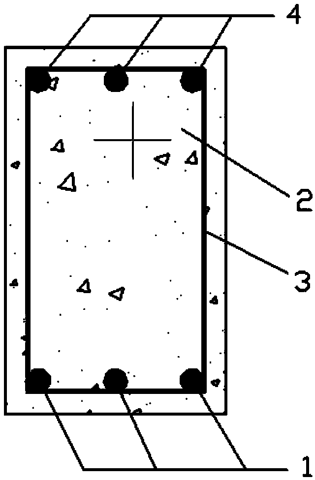
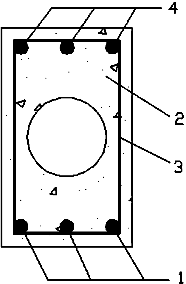
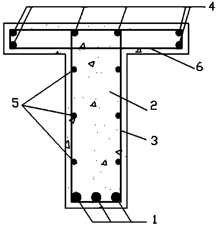
[0031] Reference attachment Figure 1-4 , FRP bar fiber high-strength concrete beam members, including fiber high-strength concrete and pouring FRP bar skeleton: the cross-sectional shape of the beam member has solid rectangle, hollow rectangle, T-shape and box shape; for rectangular and hollow rectangular cross-sections, so The FRP rib skele...


PUM


Abstract

The invention relates to an FRP (Fiber Reinforced Plastic) bar and fiber high-strength concrete beam component. The FRP (Fiber Reinforced Plastic) bar and fiber high-strength concrete beam component comprises fiber high-strength concrete and an FRP bar framework cast in the fiber high-strength concrete, wherein the cross section of the beam component is solid rectangular, hollow rectangular, T-shaped or box-shaped; for the solid rectangular or hollow rectangular cross section, the FRP bar framework consists of longitudinal strained FRP bars, FRP stirrup bars and longitudinal erected FRP bars, and the longitudinal strained FRP bars and the longitudinal erected FRP bars are attached to the inner sides of the FRP stirrup bars and bundled together; for the T-shaped cross section and the box-shaped cross section, the FRP bar framework consists of longitudinal strained FRP bars, FRP stirrup bars, erected FRP bars, girder web distributed FRP bars and top plate stressed FRP bars, the longitudinal strained FRP bars are attached to the inner sides of the FRP stirrup bars, the distributed FRP bars are attached to the inner sides of the FRP stirrup bars, the erected FRP bars are attached to the inner sides of the top plate stressed FRP bars, and the top plate stressed FRP bars are connected with the FRP stirrup bars to form effective connection.

Description

Technical field [0001] The invention relates to a FRP bar fiber high-strength concrete beam component, which belongs to the field of construction, bridge and port engineering. Background technique [0002] At present, ordinary reinforced concrete beams widely used in the fields of construction, bridges and port engineering have the following defects: ordinary concrete has poor crack resistance and can only use non-high-strength steel bars, which limits the use of high-strength steel bars; due to the low strength of concrete and steel bars, Only relying on the method of increasing the size of the beam section and adding reinforced steel bars to increase its bearing capacity will not only cause great material loss, increase construction costs and construction difficulties, but also severely compress the available space due to the large cross section; the tensile strength of concrete materials is low , The concrete in the tension zone has cracked under the action of much lower load ...

Claims


Application Information

Patent Timeline
IPC IPC(8): E04C3/20
Inventor 朱海堂高丹盈张启明李金章孙丽萍
Owner ZHENGZHOU UNIV
Why Eureka
Try Eureka