
Fluid dynamic machine with turning wheel transmission piston speed-changing mechanism

A technology of speed change mechanism and transmission piston, applied in rotary piston machinery, rotary or oscillating piston engine, rotary piston engine, etc., can solve the problem of poor stability, affecting the structural performance of piston compressor and piston engine, complex structure, etc. question

Inactive Publication Date: 2015-01-07
南通金鼎天轮动力科技有限公司
View PDF4 Cites 5 Cited by
  • Summary
  • Abstract
  • Description
  • Claims
  • Application Information

AI Technical Summary

Problems solved by technology

When the piston compresses the gas, the stroke of the piston is not proportional to the back pressure on the piston after the gas is compressed. The above defects are unavoidable in the piston crankshaft and connecting rod mechanism. This defect seriously affects the structural performance of the piston compressor and piston engine. There is an urgent need for a piston speed change mechanism that adapts to changes in gas pressure to replace the existing piston crankshaft linkage mechanism. I applied for a patent on June 27, 2014, application number: Patent name: with a rotary piston speed change mechanism Fluid power machinery, but this invention still has defects such as complex structure and poor stability, and needs to be further improved

Method used


Image

  • Fluid dynamic machine with turning wheel transmission piston speed-changing mechanism
  • Fluid dynamic machine with turning wheel transmission piston speed-changing mechanism
  • Fluid dynamic machine with turning wheel transmission piston speed-changing mechanism

Examples


Embodiment Construction

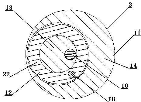
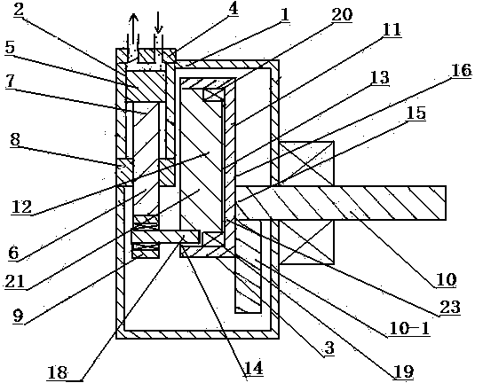
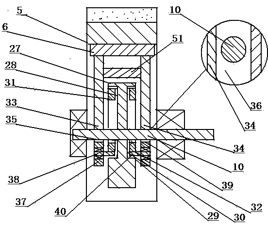
[0029] Such as figure 1 , figure 2 , image 3 As shown, the rotary transmission piston speed change mechanism is made up of body 1, cylinder-piston linkage 2 and rotary transmission mechanism 3. Such as figure 2As shown, the cylinder-piston linkage mechanism 2 is composed of a cylinder 4, a piston 5 and a connecting rod 6, the cylinder 4 is fixed on the body 1, the bottom of the piston 5 and the rod body 7 of the connecting rod 6 are fixed to each other, and the rod body 7 of the connecting rod 6 is outside Covered with a sliding sleeve 8, the sliding sleeve 8 is fixed on the inner wall of the body 1 or fixed on the bottom of the cylinder 4, the rod body 7 linearly slides in the sliding sleeve 8, and the tail of the connecting rod 6 is fixed with a connecting rod sleeve 9. The runner transmission mechanism 3 is made up of transmission shaft 10 , runner disc 11 and runner body 12 . Such as figure 2 As shown, the bearing support at one end of the transmission shaft 10 is...


PUM


Abstract

The invention relates to a fluid dynamic machine with a turning wheel transmission piston speed-changing mechanism. The fluid dynamic machine comprises a machine body (1), an air cylinder piston linkage mechanism (2) and a turning wheel transmission mechanism (3), wherein a turning wheel disc (11) and a transmission shaft (10) of the turning wheel transmission mechanism (3) are concentrically or eccentrically mounted, a turning wheel groove (13) is formed in a disc surface (14) of the turning wheel disc (11), a turning wheel body (12) is supported and mounted in the turning wheel groove (13) through a bearing, a rotating shaft (18) is mounted on the turning wheel body (12), and a connecting rod sleeve (9) at the tail of a connecting rod (6) sleeves the outer part of the rotating shaft (18); the turning wheel disc (11) rotates, and the turning wheel body (12) drives the connecting rod (6) and a piston (6) to do the variable-speed reciprocating motion.

Description

technical field [0001] The invention relates to a rotary transmission piston transmission mechanism for fluid machinery and engines, and relates to the technical field of fluid power machinery manufacturing such as fans, compressors, expansion power machines and engines. Background technique [0002] What used piston compressor and piston engine adopted at present is a piston crankshaft connecting rod mechanism, and the piston crankshaft connecting rod mechanism becomes the reciprocating motion of piston by crankshaft rotation. When the piston compresses the gas, the stroke of the piston is not proportional to the back pressure on the piston after the gas is compressed. The above defects are unavoidable in the piston crankshaft and connecting rod mechanism. This defect seriously affects the structural performance of the piston compressor and piston engine. There is an urgent need for a piston speed change mechanism that adapts to changes in gas pressure to replace the existi...

Claims


Application Information

Patent Timeline
Patent Type & Authority Applications(China)
IPC IPC(8): F01C1/356F04C2/356F04C18/356F02B55/00F02B53/00
CPCF01C1/356F01C21/00F04C2/356F04C15/00Y02T10/12
Inventor 周觉明
Owner 南通金鼎天轮动力科技有限公司
Learn More