Refrigerant recovery process and system of refrigerating system
A refrigerant recovery and refrigeration system technology, applied in the field of low temperature systems, can solve problems such as waste, and achieve the effects of increasing energy consumption, wide application range and reducing energy consumption
- Summary
- Abstract
- Description
- Claims
- Application Information
AI Technical Summary
Problems solved by technology
Method used
Image

Examples
Embodiment 1
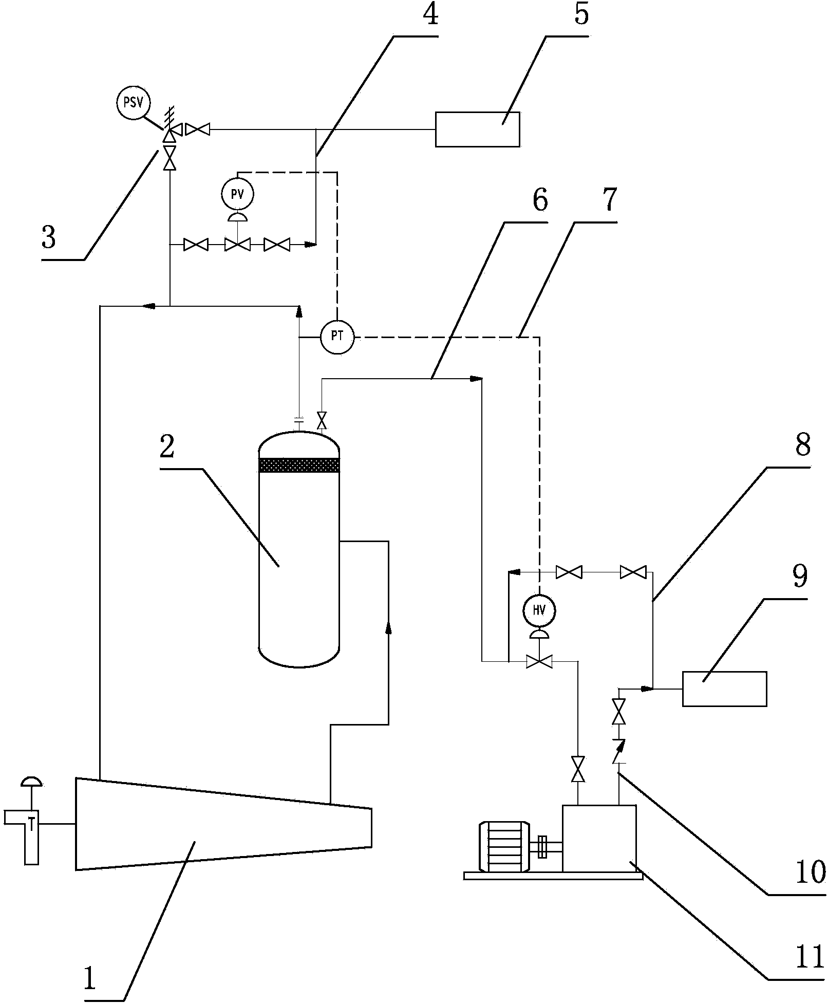
[0029] Such as figure 1 As shown, the refrigeration system refrigerant recovery system includes a buffer tank 2, a refrigeration system compressor 1, the refrigeration system compressor 1 is connected to the buffer tank 2, and the buffer tank 2 is connected to the flare system 5 through the safety valve system 3 and the pressure regulating valve system 4.
[0030] The buffer tank 2 is connected to a screw compressor 11 through the inlet pipeline 6, and the screw compressor 11 is connected to the storage tank 9 through the outlet pipeline 10. Both the inlet pipeline 6 and the outlet pipeline 10 are provided with control valves, and between the inlet pipeline 6 and the outlet pipeline 10 It is connected through the import and export cross-line 8, and a control valve is arranged on the import and export cross-line 8. The inlet line 6 is associated with the pressure regulating valve system 4 and the safety valve system 3 through the pressure signal line 7 .
[0031] The refrigera...
Embodiment 2
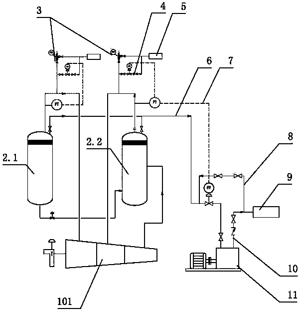
[0033] Such as figure 2 As shown, the refrigerant recovery system of the ethylene refrigeration system includes a first-stage inlet buffer tank 2.1, a second-stage inlet buffer tank 2.2, and an ethylene compressor 101. The ethylene compressor 101 is connected to the first-stage inlet buffer tank 2.1, and the second-stage inlet The buffer tank 2.2, the first stage inlet buffer tank 2.1 and the second stage inlet buffer tank 2.2 are connected to the flare system 5 through the safety valve system 3 and the pressure regulating valve system 4 respectively.
[0034] The first-stage inlet buffer tank 2.1 and the second-stage inlet buffer tank 2.2 are respectively connected to the screw compressor 11 through respective inlet pipelines 6, and the screw compressor 11 is connected to the storage tank 9 through the outlet pipeline 10. A control valve is provided, and the inlet pipeline 6 of the two-stage buffer tank is respectively connected to the outlet pipeline 10 through an inlet and...
Embodiment 3
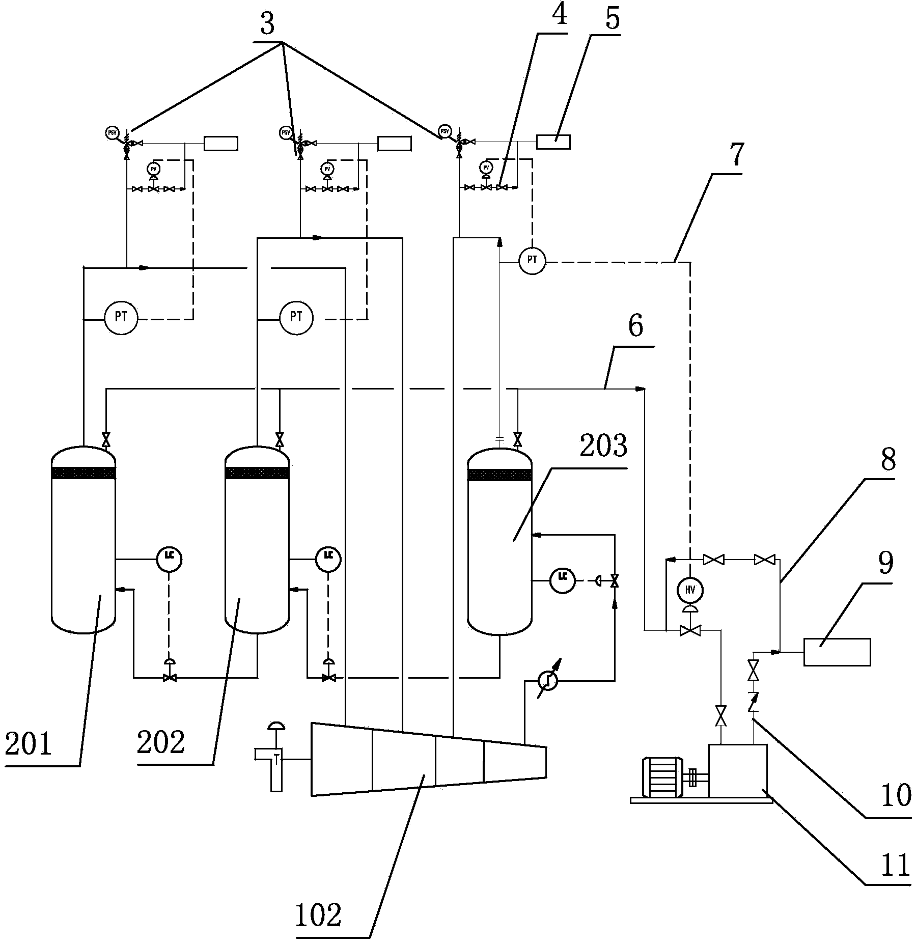
[0038] Such as image 3As shown, the refrigerant recovery system of the propylene refrigeration system includes a first-stage inlet buffer tank 201, a second-stage inlet buffer tank 202, and a propylene compressor 102. The propylene compressor 102 is connected to the first-stage inlet buffer tank 201, and the second-stage inlet The buffer tank 202, the third-stage inlet buffer tank 203, the first-stage inlet buffer tank 201, the second-stage inlet buffer tank 202, and the third-stage inlet buffer tank 203 are respectively connected to the flare system through the safety valve system 3 and the pressure regulating valve system 4 5.
[0039] The first-stage inlet buffer tank 201, the second-stage inlet buffer tank 202, and the third-stage inlet buffer tank 203 are respectively connected to the screw compressor 11 through respective inlet pipelines 6, and the screw compressor 11 is connected to the storage tank 9 through the outlet pipeline 10, and the inlet Both the pipeline 6 a...
PUM
 Abstract
Description
Claims
Application Information
 - R&D
- Intellectual Property
- Life Sciences
- Materials
- Tech Scout
- Unparalleled Data Quality
- Higher Quality Content
- 60% Fewer Hallucinations
Browse by: Latest US Patents, China's latest patents, Technical Efficacy Thesaurus, Application Domain, Technology Topic, Popular Technical Reports.
© 2025 PatSnap. All rights reserved.Legal|Privacy policy|Modern Slavery Act Transparency Statement|Sitemap|About US| Contact US: help@patsnap.com