Particulate matter sensor and particulate matter monitoring method

A particle sensor and particle technology, applied in the field of photoelectric detection, can solve the problems of large error in monitoring results, low optical energy density, and large detection area of ​​the monitoring light source, and achieve the effect of small divergence angle and high optical energy density

Inactive Publication Date: 2015-01-07
北京云彤科技有限公司
View PDF7 Cites 26 Cited by
  • Summary
  • Abstract
  • Description
  • Claims
  • Application Information

AI Technical Summary

Problems solved by technology

[0005] Infrared LED is used as the monitoring light source in the particle sensor. Although it is focused by the lens, the detection area of ​​the monitoring light source is relatively large, and the optical energy density of the optical signal per unit area of ​​the detection area is low. It is only suitable for industrial and mining enterprises with large diameters. Monitoring of particulate matter or high concentration dust
When monitoring particles with a diameter of less than 1 μm, since the light energy of the light signal scattered by the particles is very small, the infrared detector cannot detect it, resulting in the above-mentioned particle sensor having low sensitivity when monitoring particles with a diameter of less than 1 μm
Therefore, when the above-mentioned particle sensor based on infrared LED monitors the concentration of PM2.5 particles, the error of the monitoring result is relatively large

Method used


Image

  • Particulate matter sensor and particulate matter monitoring method
  • Particulate matter sensor and particulate matter monitoring method
  • Particulate matter sensor and particulate matter monitoring method

Examples


Embodiment 1

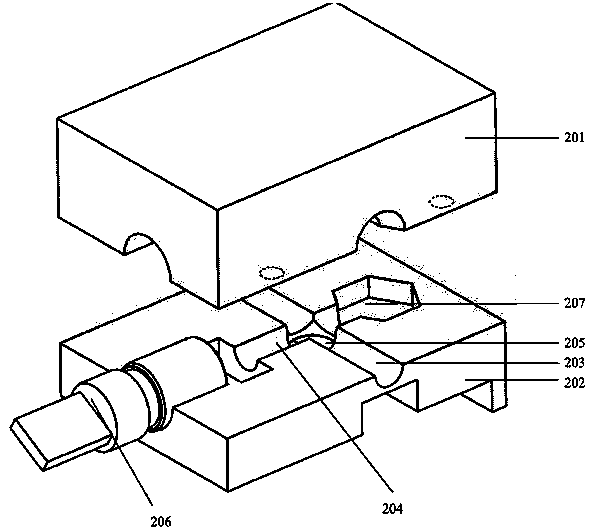
[0065] figure 2 It is a structural schematic diagram of Embodiment 1 of a particulate matter sensor in the present invention, and the particulate matter sensor includes:

[0066] The upper cover 201 and the base 202 , the upper cover 201 and the base 202 form a light-shielding space including an air flow channel 203 and a light transmission channel 204 .

[0067] The light-shielding space of the particle sensor is formed by the combination of the upper cover 201 and the base 202 , and the light-shielding space formed by the upper cover 201 and the base 202 includes an air flow channel 203 and a light transmission channel 204 .

[0068] like figure 2 As shown, the airflow passage 203 is a cylindrical passage through the particle sensor formed by a semicircular groove of the upper cover 201 and a semicircular groove of the base 202 . It should be noted here that the air flow channel 203 is not limited to figure 2 Cylindrical channels are shown in , but other shapes such as...

Embodiment 2

[0125] Figure 8 It is a flow chart of Embodiment 2 of a particulate matter monitoring method of the present invention. The method is a particulate matter monitoring method implemented by using the particulate matter sensor described in Embodiment 1. The method includes:

[0126] Step 801: Start the laser to output a laser beam in the optical transmission channel, the laser beam irradiates particles in the monitoring airflow in the intersecting area of ​​the airflow channel and the optical transmission channel to scatter, and the monitoring airflow enters from one end of the airflow channel.

[0127] The monitoring airflow enters from one end of the airflow channel and exits from the other end of the airflow channel. Optionally, during specific implementation, the exhaust fan can be started, and the exhaust fan will discharge the air in the chamber from the particle sensor, and a negative pressure will be generated in the chamber, so that the monitored airflow enters the airfl...


PUM

PropertyMeasurementUnit
diameteraaaaaaaaaa

Abstract

The invention provides a particulate matter sensor and a particulate matter monitoring method. The particulate matter sensor comprises an upper cover and a base which form a light shading space comprising an airflow channel and a light transmission channel, wherein the airflow channel is perpendicular to the light transmission channel, and a photoelectric detector is arranged under the crossed region of the airflow channel and the light transmission channel; a laser device is arranged at one end of the light transmission channel, and a light absorption device is arranged at the other end of the light transmission channel; a PCB (Printed Circuit Board) circuit is connected with the photoelectric detector; a laser beam output by the laser device is adopted as a monitoring light source in the particulate matter sensor, so that a light signal generated by laser scattering of particulate matters still can be monitored by the photoelectric detector even if the PM2.5 particulate matters or the particulate matters with relatively small diameters are monitored as laser is collimating light with small divergence angle and high light energy density in unit area, and the monitoring accuracy of the particulate matter sensor during monitoring of the PM2.5 particulate matters or the particulate matters with relatively small diameters in air is improved.

Description

technical field [0001] The invention relates to the technical field of photoelectric detection, in particular to a particle sensor and a particle monitoring method. Background technique [0002] At present, the particle sensor is mainly used for continuous monitoring of dust concentration in mines or cement plants and other places in industry. When the dust concentration exceeds a certain limit, it is necessary to take dust suppression measures to prevent dust explosions caused by excessive dust concentration. [0003] Traditional particle sensors, such as SM-PWM-01A of GE (General Electric Company), GP2Y1010 of Sharp Company, and DSM510 of Sanyoung Company, are all particle sensors based on infrared light scattering method. like figure 1 As shown, the particle sensor consists of an infrared light-emitting diode (LED), two focusing lenses, an infrared detector, and a signal processing circuit. Wherein, there is a certain included angle between the transmission direction o...

Claims


Application Information

Patent Timeline
Patent Type & Authority Applications(China)
IPC IPC(8): G01N15/06
Inventor 崔海林
Owner 北京云彤科技有限公司
Why Eureka
Try Eureka