Special breaker circuit for miniature prepaid electricity meter

A technology of prepaid electric meters and circuit breakers, which is applied in the direction of instruments, coinless or similar appliances, and coin-operated equipment for renting items, etc. It can solve the problems of inability to distinguish and improve the continuity of power supply, and achieve improved Accuracy, strong anti-electromagnetic compatibility characteristics, and simple circuit design

Inactive Publication Date: 2015-01-07
CNC ELECTRIC GRP
View PDF6 Cites 4 Cited by
  • Summary
  • Abstract
  • Description
  • Claims
  • Application Information

AI Technical Summary

Problems solved by technology

[0004] The technical problem to be solved by the present invention is that, in view of the above-mentioned defects in the prior art, it is impossible to distinguish whether the product tripping is caused by the control of the electric energy metering device or the product tripping is caused by other reasons, and the continuity of power supply cannot be improved. A special circuit breaker circuit for a small prepaid electric meter, comprising: a power input, a power circuit, a delay trip circuit connected to the power circuit, a closing and opening feedback signal circuit, an electric energy measurement detection circuit of an electric meter, and an electric energy measurement circuit of the electric meter The detection circuit is connected to the delay release circuit; wherein, the source circuit includes a piezoresistor RV1, a rectifier diode D3, a current limiting resistor R5, a diode D5 and a voltage regulator diode D4; the delay release circuit includes a diode D2, Resistors R3, R4, capacitors C2, C3, silicon controlled rectifier Q1 and release S2; the electric energy metering detection circuit of the electric meter includes piezoresistor RV2, resistors R1, R2, diode D1, capacitor C1 and transistor Q2; The gate opening feedback signal circuit includes the closing and opening detection switch S1 and the current limiting resistor R6

Method used


Image

  • Special breaker circuit for miniature prepaid electricity meter
  • Special breaker circuit for miniature prepaid electricity meter

Examples


Embodiment Construction

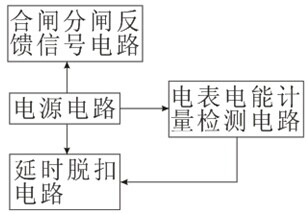
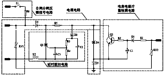
[0011] see figure 1 , is the schematic circuit block diagram of the first embodiment of the circuit breaker circuit dedicated to the small prepaid electric meter of the present invention. figure 2 yes figure 1 circuit schematic diagram. Such as figure 1 , figure 2 As shown, in the circuit breaker circuit for small prepaid electric meters provided in the first embodiment of the present invention, at least include, power input, power circuit, delay trip circuit connected with the power circuit, closing and opening feedback signal circuit, electric energy measurement detection circuit of the electric meter, the electric energy measurement detection circuit of the electric meter is connected with the time-delay tripping circuit; wherein, the source circuit includes a piezoresistor RV1, a rectifier diode D3, a current limiting resistor R5, a diode D5 and a Zener diode D4; the delay tripping circuit includes diode D2, resistors R3, R4, capacitors C2, C3, silicon controlled rec...


PUM


Abstract

The invention relates to a special breaker circuit for a miniature prepaid electricity meter. The special breaker circuit comprises a power supply input, and is characterized by further comprising a power supply circuit, and a delay trip circuit, a switch-on and switch-off feedback signal circuit, an electricity meter electric energy measurement detecting circuit connected to the power supply circuit, wherein a source circuit comprises a piezoresistor RV1, a rectifier diode D3, a current-limiting resistor R5, a diode D5 and a voltage stabilizing diode D4; the delay trip circuit comprises a diode D2, resistors R3 and R4, capacitors C2 and C3, a silicon controlled rectifier Q1 and a tripper S2; the electricity meter electric energy measurement detecting circuit comprises a piezoresistor RV2, resistors R1 and R2, a diode D1, a capacitor C1 and a transistor Q2; the switch-on and switch-off feedback signal circuit comprises a switch-on and switch-off detecting switch S1 and a current-limiting resistor R6. According to the special breaker circuit for the miniature prepaid electricity meter, measuring accuracy of the electric energy, and continuity, reliability and safety of power supply are greatly improved; delay precision and reliability are improved, design is simple and resistance to electromagnetic compatibility is strong.

Description

technical field [0001] The invention relates to the technical field of circuit breakers, in particular to a special circuit breaker circuit for small prepaid electric meters. Background technique [0002] With the continuous deepening of the transformation of the national power grid, the use of electric energy metering devices such as circuit breakers for small prepaid meters is becoming more and more popular. The schematic block diagram of the special circuit breaker circuit for electricity consumption meters includes: a power supply circuit, a delay trip circuit and an electric energy metering detection circuit for electric meters. Since there is no closing and opening signal feedback circuit, it is impossible to distinguish whether the tripping of the product is caused by the control of the electric energy metering device or due to Product tripping caused by other reasons cannot improve the continuity of power supply. [0003] Therefore, prior art urgently needs to have ...

Claims


Application Information

Patent Timeline
IPC IPC(8): G07F15/06
Inventor 余存泰肖义峰章火明黎永胜李其利彭昆明
Owner CNC ELECTRIC GRP
Why Eureka
Try Eureka