
Reflection array antenna for co-frequency co-time full duplex system

A technology of co-frequency full-duplex and reflective array antennas, applied in the field of reflective array antennas, to achieve the effects of expanding communication capacity, improving spectrum utilization, and improving electromagnetic compatibility

Inactive Publication Date: 2015-01-07
UNIV OF ELECTRONICS SCI & TECH OF CHINA
View PDF5 Cites 23 Cited by
  • Summary
  • Abstract
  • Description
  • Claims
  • Application Information

AI Technical Summary

Problems solved by technology

The purpose of the present invention is to solve the electromagnetic compatibility problem in the CCFD system that shares the receiving and receiving antenna, and focuses on the isolation problem between the receiving and receiving antennas

Method used


Image

  • Reflection array antenna for co-frequency co-time full duplex system
  • Reflection array antenna for co-frequency co-time full duplex system
  • Reflection array antenna for co-frequency co-time full duplex system

Examples


Embodiment

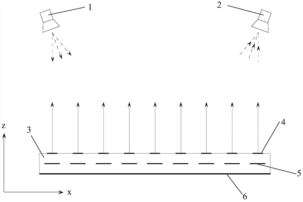
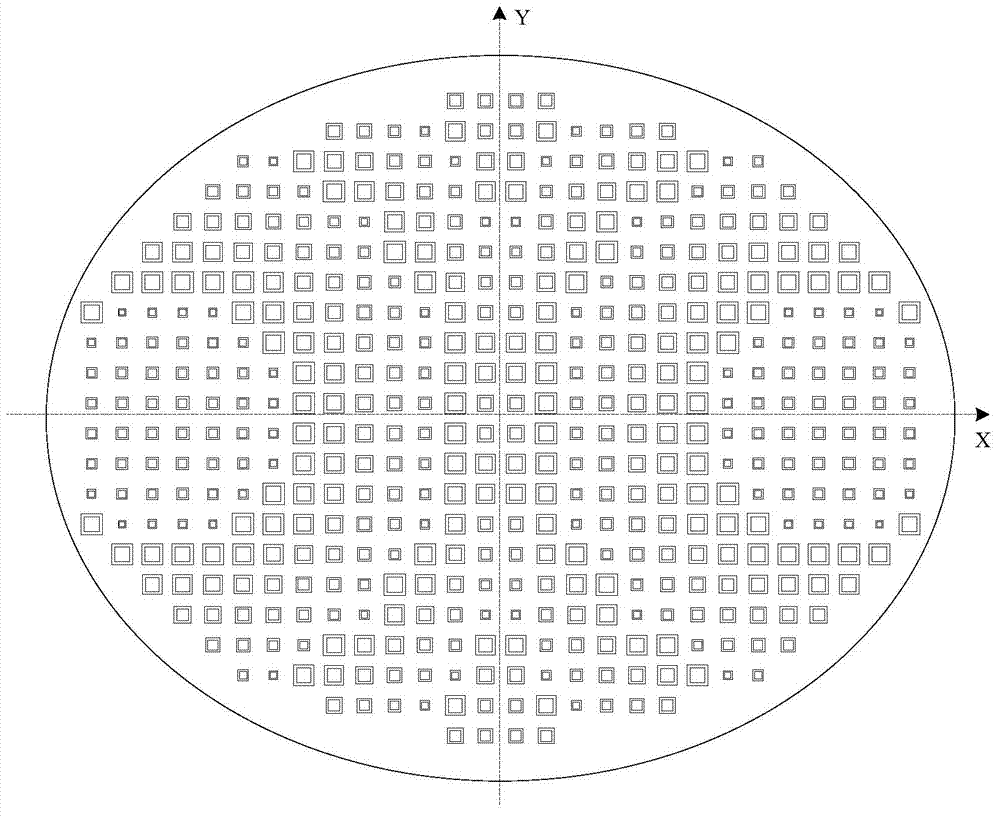
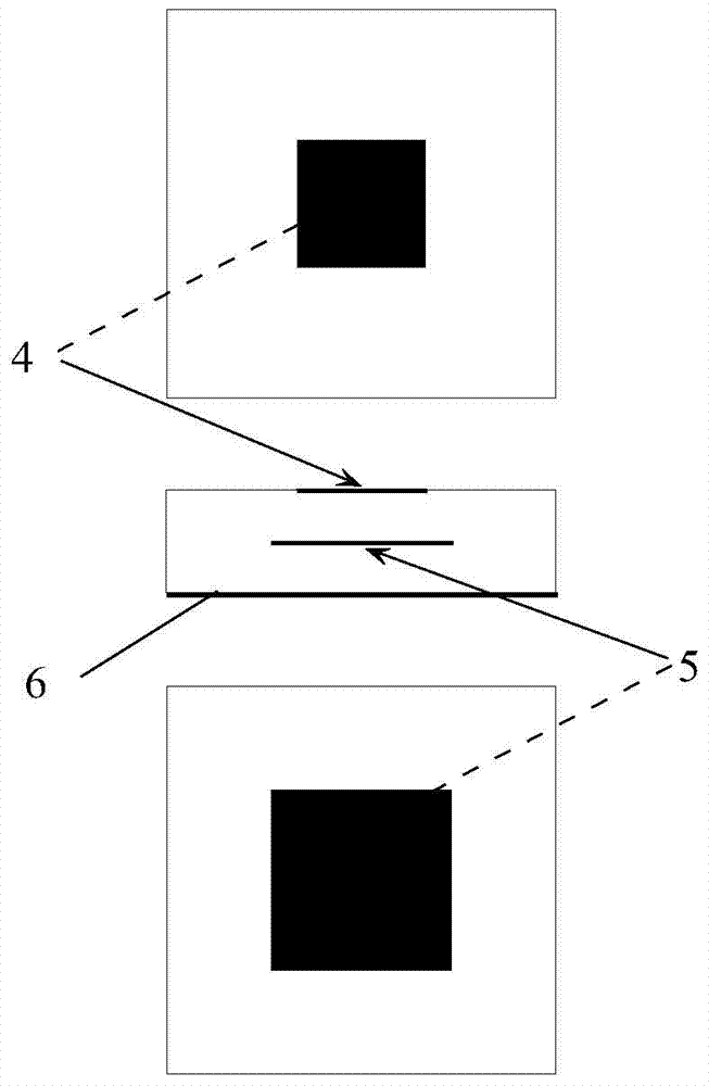
[0019] The side-view structure of the reflectarray antenna used in the simultaneous and same-frequency full-duplex system provided by this embodiment is as follows: figure 1 As shown, the central operating frequency is 15GHz, including the feed 1 at the transmitting end, the feed 2 at the receiving end, and a reflective array formed by double-layer metal patch units.

[0020] In order to facilitate the description of the positional relationship of the various components in this embodiment, an O-XYZ rectangular coordinate system is established. The origin O is located at the geometric center of the metal floor of the reflection array, the X axis coincides with the long axis of the elliptical reflection array, and the Y axis coincides with the long axis of the elliptical reflection array. The short axis of the array coincides, and the Z axis is the normal direction of the reflector array.

[0021] In this embodiment, the feed source 1 at the transmitting end and the feed source ...


PUM


Abstract

The invention discloses a reflection array antenna for a co-frequency co-time full duplex system (CCFD). The system can receive and emit signals which have the same working efficiency and are polarized in the same direction. The system comprises an emitting end feed source, a receiving end feed source and a reflection array. The emitting end feed source and the receiving end feed source are arranged on the same side of the reflection array in a side feeding mode and are in mirror symmetry about the reflection array. The reflection array is formed by double-layer metal patch units, and the sizes of upper metal patches of the each double-layer metal patch unit are smaller than those of corresponding lower metal patches. The sizes of the patches of the patch units in the reflection array are adjusted to conduct phase compensation on the corresponding patch units, so that a pencil beam in the array face normal direction is formed after the reflection array is illuminated by the emitting end feed source, and the receiving end feed source receives an incoming wave signal in the array face normal direction. Meanwhile, high enough isolation is provided between the receiving feed source and the emitting feed source so as to ensure the good electromagnetic compatibility of the system.

Description

technical field [0001] The invention relates to the technical field of antennas for wireless communication, in particular to a reflect array antenna for simultaneous and same-frequency full-duplex systems. Background technique [0002] With the application and rapid development of wireless communication technology, wireless communication has become an indispensable means of interaction for individuals and society. The current wireless spectrum resources are nearly exhausted, while the demand for spectrum resources by wireless communication services is increasing exponentially. In order to make full use of limited spectrum resources, simultaneous and same-frequency full-duplex technology emerged as the times require. Different from the existing frequency division duplex (Frequency Division Duplex, FDD) and time division duplex (Time Division Duplex, TDD), simultaneous co-frequency full duplex (Co-frequency Co-time Full Duplex, CCFD) wireless communication is in Under the sa...

Claims


Application Information

Patent Timeline
Patent Type & Authority Applications(China)
IPC IPC(8): H01Q15/14H01Q19/10H01Q21/28
Inventor 李家林王策肖绍球王秉中
Owner UNIV OF ELECTRONICS SCI & TECH OF CHINA
Learn More