Energy feedback control method and energy feedback system
A technology of energy feedback and control method, applied in electric braking system, electric vehicle, parallel feeding arrangement of single grid, etc., can solve the problem of unstable voltage on the grid side of locomotives
- Summary
- Abstract
- Description
- Claims
- Application Information
AI Technical Summary
Problems solved by technology
Method used
Image

Examples
Embodiment 1
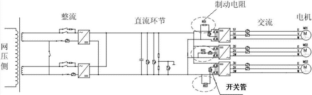
[0057] see figure 1 , which shows a schematic structural diagram of an energy feedback system provided by the present invention. Wherein, the energy feedback system includes a braking resistor, and the braking resistor is connected in series to the energy feedback system through a switch tube. Preferably, the switch tube in the present invention may be an IGBT (Insulated Gate Bipolar Transistor, insulated gate bipolar transistor).
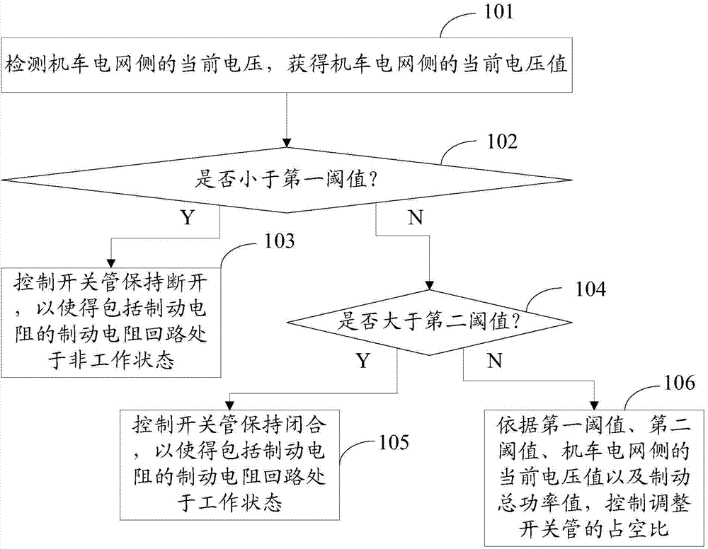
[0058] Also, see figure 2 , which shows a flowchart of an energy feedback control method provided by the present invention, including:
[0059] Step 101, detecting the current voltage of the locomotive grid side, and obtaining the current voltage value of the locomotive grid side.
[0060] Step 102, judging whether the current voltage value of the locomotive grid side is less than the first threshold; if less, perform step 103, and if not, perform step 104.
[0061] In the present invention, the first threshold is a value used to indicate that...
Embodiment 2
[0093] Based on the energy feedback control method provided by the previous invention, the present invention also provides an energy feedback system, such as Figure 5 As shown, it shows a schematic structural diagram of an energy feedback system provided by the present invention, including: a detection module 100 , a first judging module 200 , a second judging module 300 and a control module 400 . in,
PUM
 Abstract
Description
Claims
Application Information