

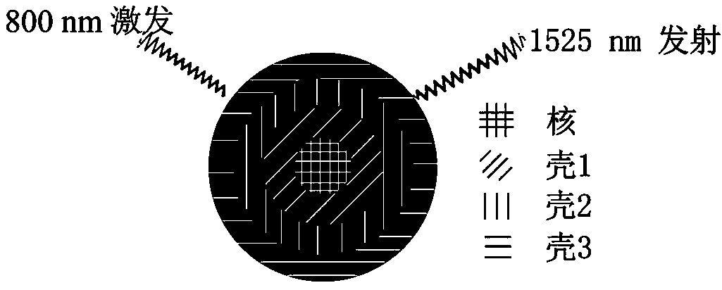
800nm-near-infrared-excited 1525nm-shortwave-infrared-emission fluorescence nano material and synthesis method thereof
A fluorescent nanomaterial and short-wave infrared technology, which is applied in the direction of luminescent materials, chemical instruments and methods, etc., can solve the problems of surrounding cells or tissue damage, and achieve the effect of low detection limit and deep penetration depth
- Summary
- Abstract
- Description
- Claims
- Application Information
AI Technical Summary
Problems solved by technology
Method used
Image

Examples
Embodiment 1
[0024] (1) Preparation of the shell precursor.
[0025] Preparation of Yb, Er-OA (0.1 M) precursor: take a 50 mL three-neck round bottom flask as a reaction vessel, add 2.45 mmol YbCl 3 , 0.05 mmol ErCl 3 , 10 mL oleic acid (OA), 15 mL octadecene (ODE). Heated to 140 °C for 1 hour under vacuum and magnetic stirring conditions, and finally a clear and transparent Yb, Er-OA (0.1 M) precursor was obtained.
[0026] Preparation of Y, Yb-OA (0.1M) precursor: The preparation of Y, Yb-OA (0.1M) precursor is similar to the preparation of the above Yb, Er-OA (0.1 M) precursor, the above 2.45 mmol YbCl 3 , 0.05 mmol ErCl 3 Replaced with 2.25 mmol YCl, respectively 3 , 0.25 mmol YbCl 3 .
[0027] Preparation of Nd, Yb-OA (0.1M) precursor: The preparation of Nd, Yb-OA (0.1M) precursor is similar to the preparation of the above-mentioned Yb, Er-OA (0.1 M) precursor, and the above-mentioned 2.45 mmol YbCl 3 , 0.05 mmol ErCl 3 , 10 mL oleic acid (OA), 15 mL octadecene (ODE) were re...
Embodiment 2
[0038] Example 2: NaGdF prepared in embodiment 1 4 NaYbF 4 :ErNaYF 4 :YbNaNdF 4 : The surface of the Yb core-shell 1-shell 2-shell 3-core-shell structure nanocrystal is hydrophobic, and the modified amphiphile molecule can make the obtained nanocrystal water-soluble, so that it has better biocompatibility. The obtained water-soluble nanocrystals are incubated with cells, and the nanocrystals can enter cells through endocytosis. According to the short-wave infrared down-conversion fluorescence of the nanocrystals, the cells can be imaged with an infrared camera. In addition, the obtained water-soluble nanocrystals are injected into the mice through the tail vein, and the short-wave infrared down-conversion fluorescence of the nanocrystals can be used for in vivo imaging. Due to the precise optimization of this synthesis method and the advantage of 800 nm excitation light, the NaGdF 4 NaYbF 4 :ErNaYF 4 :YbNaNdF 4 : Yb core-shell 1-shell 2-shell 3-core-shell nanocrystals...
PUM
 Abstract
Description
Claims
Application Information