Nitrogen displacement system for LNG (Liquefied Natural Gas) storage tank

A nitrogen replacement and storage tank technology, which is applied to fixed-capacity gas storage tanks, container discharge methods, and equipment loaded into pressure vessels. and other problems, to achieve the effect of speeding up the nitrogen replacement time and shortening the drying and inerting time.

Active Publication Date: 2015-01-14
CHINA NAT OFFSHORE OIL CORP +1
View PDF8 Cites 18 Cited by
  • Summary
  • Abstract
  • Description
  • Claims
  • Application Information

AI Technical Summary

Problems solved by technology

The disadvantage of the traditional nitrogen replacement scheme is that there are too few holes for the nitrogen pipeline, especially after the concrete leveling layer is selected, the nitrogen replacement stage is very difficult
The upper and lower parts of the insulation layer of foam glass bricks at the bottom of the storage tank are concrete leveling layers. During the process of nitrogen replacement at the bottom of the tank, water molecule vapor continuously seeps out of the concrete molecules. Later, the water vapor brought out by the nitrogen replacement airflow and the concrete leveling layer The water vapor constantly seeping out of the tank forms a dynamic balance. It is difficult for the general tank bottom nitrogen replacement system to achieve a good water vapor replacement effect on the heat insulation layer. Therefore, after the LNG storage tank is put into production, it is generally difficult to achieve the optimal cold insulation layer material at the bottom of the tank. The performance effect of the use

Method used


Image

  • Nitrogen displacement system for LNG (Liquefied Natural Gas) storage tank
  • Nitrogen displacement system for LNG (Liquefied Natural Gas) storage tank
  • Nitrogen displacement system for LNG (Liquefied Natural Gas) storage tank

Examples


Embodiment Construction

[0034] The present invention will be further described below in conjunction with the accompanying drawings, but the present invention is not limited to the following embodiments.

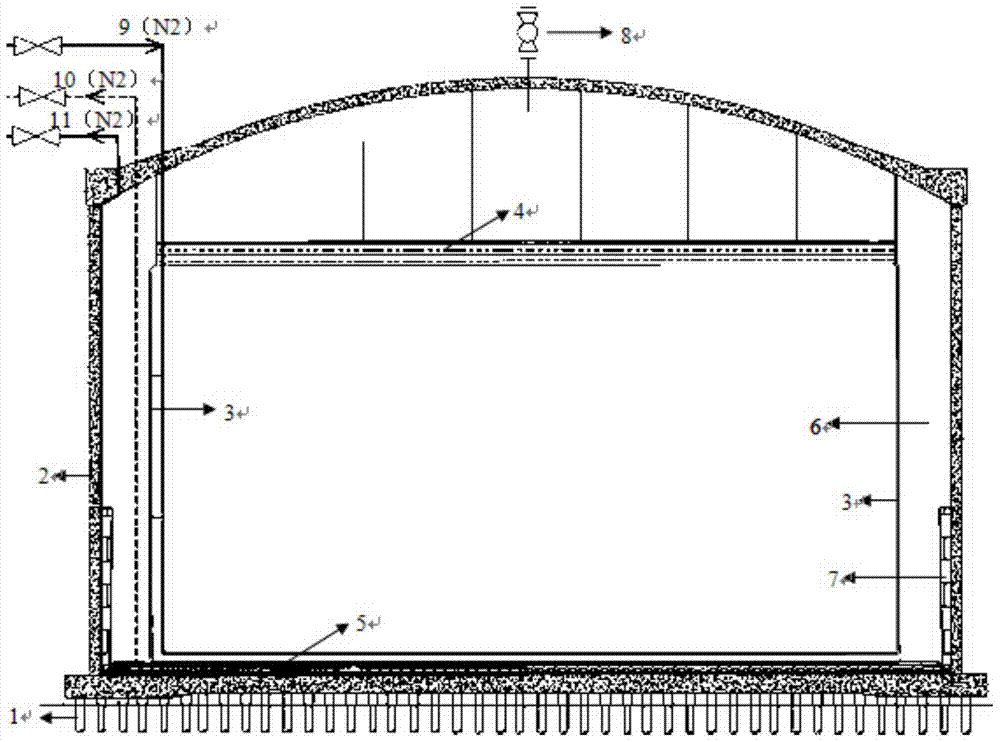
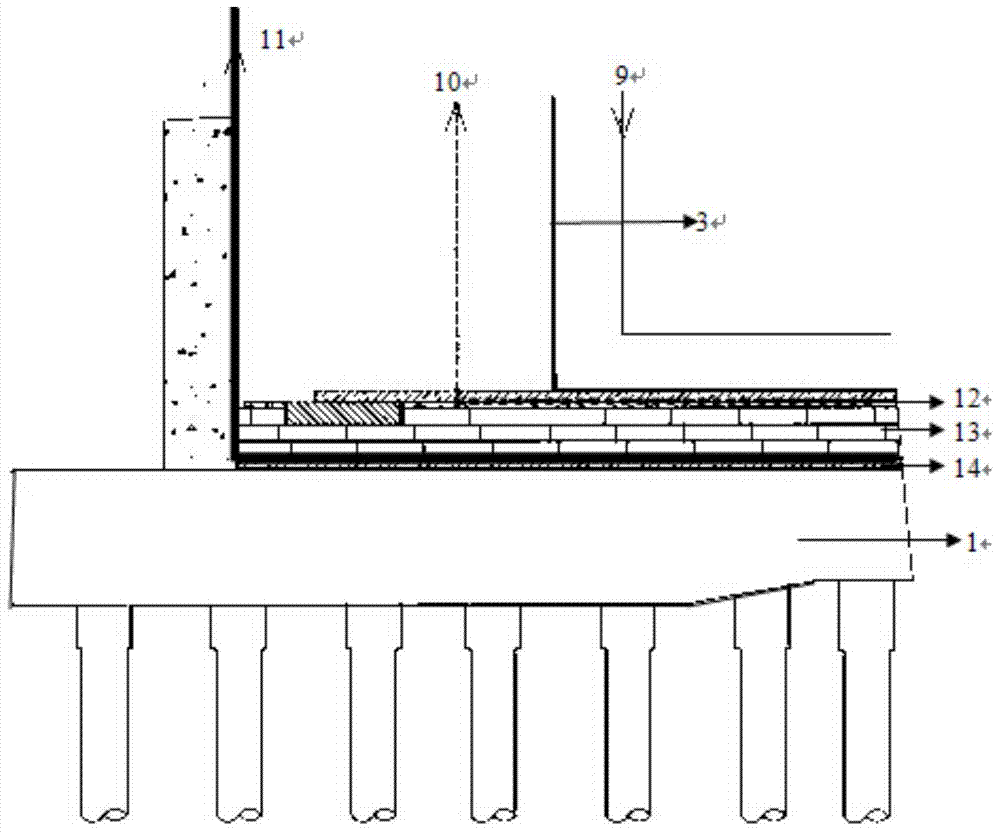
[0035] Such as figure 1 Shown is a structural schematic diagram of the cooperation of the nitrogen replacement system and the LNG storage tank provided by the present invention. The main structure of the LNG storage tank is composed of the following seven parts: pile cap foundation 1; prestressed concrete outer tank 2; inner tank 3; aluminum ceiling structure (including ceiling insulation layer) 4; tank bottom insulation layer 5; tank wall insulation layer 6; thermal corner protection system (TCP) 7. Wherein, the tank bottom insulation layer 5 includes an upper concrete leveling layer 12 , a foam glass brick pressure insulation layer 13 and a lower concrete leveling layer 14 . The nitrogen replacement system of the present invention includes a nitrogen gas inlet pipe 9, a tank top manual vent valve...


PUM


Abstract

The invention discloses a nitrogen displacement system for an LNG (Liquefied Natural Gas) storage tank. The nitrogen displacement system comprises a nitrogen inlet pipeline, a tank top emptying system for inner tank nitrogen drying replacement, a tank bottom insulation layer upper nitrogen drying replacement pipeline and a tank bottom insulation layer lower nitrogen drying replacement pipeline, wherein the nitrogen inlet pipeline extends to the bottom of the inner tank along a wall plate of the inner tank of the LNG storage tank; the tank top emptying system for inner tank nitrogen drying replacement is arranged on the top of the LNG storage tank; the tank bottom insulation layer upper nitrogen drying replacement pipeline extends into a tank bottom foam glass brick insulation layer upper concrete leveling layer along the interior of a tank wall insulation layer of the LNG storage tank; the tank bottom insulation layer lower nitrogen drying replacement pipeline extends into the tank bottom insulation layer along the tank wall insulation layer of the LNG storage tank; and the tank bottom insulation layer lower nitrogen drying replacement pipeline is arranged in a lower concrete leveling layer channel of the tank bottom insulation layer. According to the nitrogen displacement system for the LNG storage tank, after the inner tank nitrogen replacement is finished, nitrogen replacement in the annular space and the upper and lower parts of the tank bottom can be simultaneously started, the N2 gas flow is increased, and the drying inerting rate is accelerated.

Description

technical field [0001] The invention relates to a nitrogen replacement system for an LNG storage tank, belonging to the field of liquefied natural gas storage. Background technique [0002] Whether it is a natural gas liquefaction plant or an LNG receiving terminal, the investment in LNG storage tanks occupies a relatively high proportion, especially in LNG receiving terminals, the investment in storage tanks accounts for about 30-40% of the total investment. It can be seen that LNG storage tanks It is a very important part of the entire LNG industry chain. [0003] Liquefied natural gas (LNG) is stored in large LNG full-containment tanks at atmospheric pressure (gauge pressure less than 50kPa) and low temperature (-162°C). Due to contact with ultra-low temperature LNG, if there is water vapor in the bottom, wall and inner tank of the storage tank, it will In low temperature environment, it is easy to make the cold insulation effect of the bottom, wall and roof of the stora...

Claims


Application Information

Patent Timeline
Patent Type & Authority Applications(China)
IPC IPC(8): F17C7/00F17C5/00F17C13/00
Inventor 张超扬帆屈长龙陈锐莹段品佳肖立
Owner CHINA NAT OFFSHORE OIL CORP
Why Eureka
Try Eureka