Illumination system for optical detection, detection system and method using the same

A lighting system and optical inspection technology, applied in the field of optical inspection, can solve problems such as back reflection and wire defects

Inactive Publication Date: 2015-01-14
MACHVISION INC
View PDF7 Cites 15 Cited by
  • Summary
  • Abstract
  • Description
  • Claims
  • Application Information

AI Technical Summary

Problems solved by technology

[0004] However, this method often has dust or other attachments on the metal wires, because the attachments will scatter the forward incident light, so that the metal wires under the attachments can

Method used


Image

  • Illumination system for optical detection, detection system and method using the same
  • Illumination system for optical detection, detection system and method using the same
  • Illumination system for optical detection, detection system and method using the same

Examples


Example Embodiment

[0053] In order to fully understand the purpose, features and effects of the present invention, the following specific embodiments are now used in conjunction with the accompanying drawings to give a detailed description of the present invention. The description is as follows:

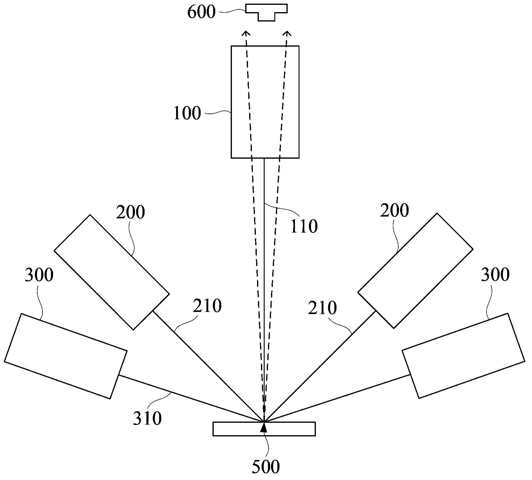
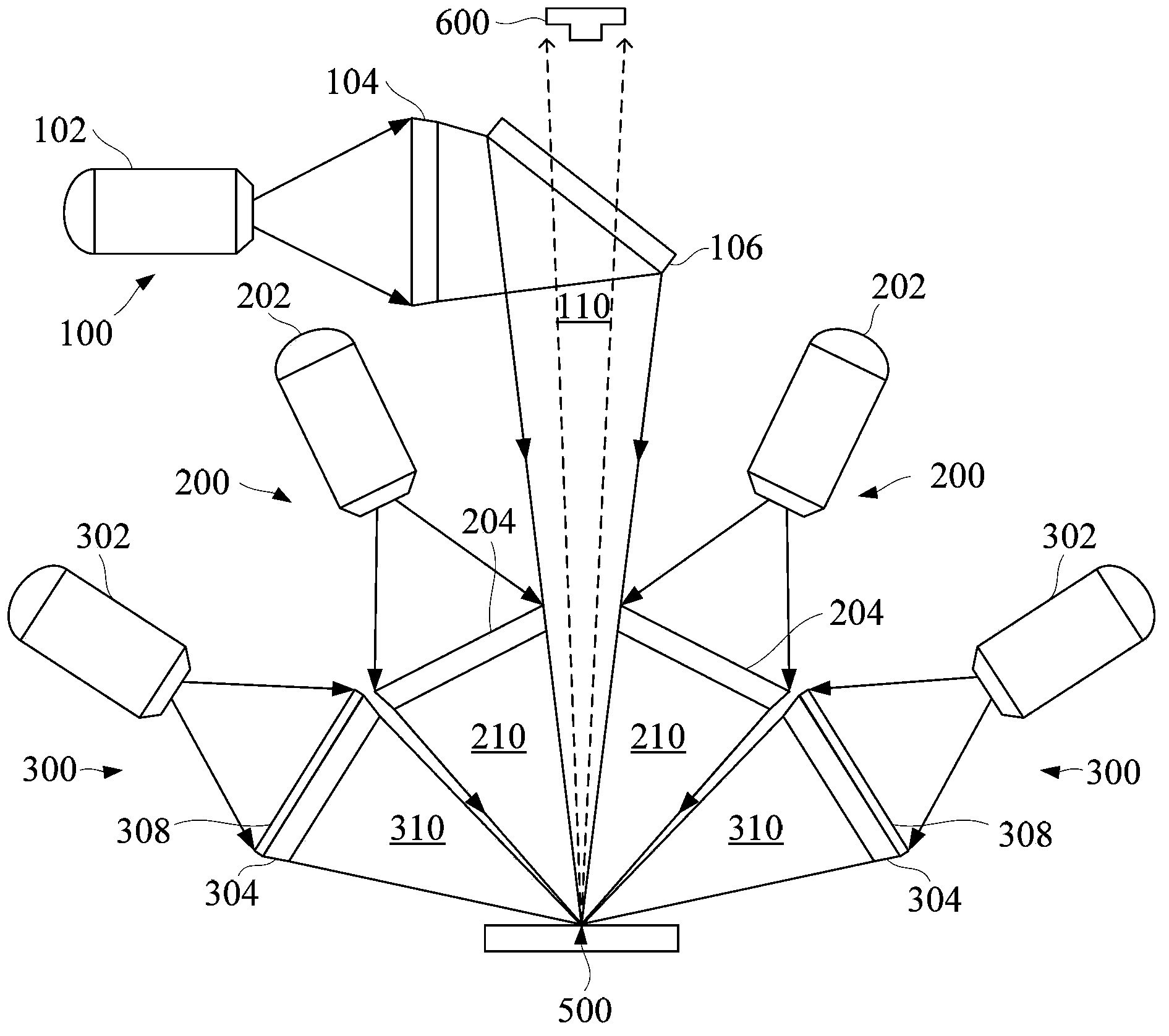
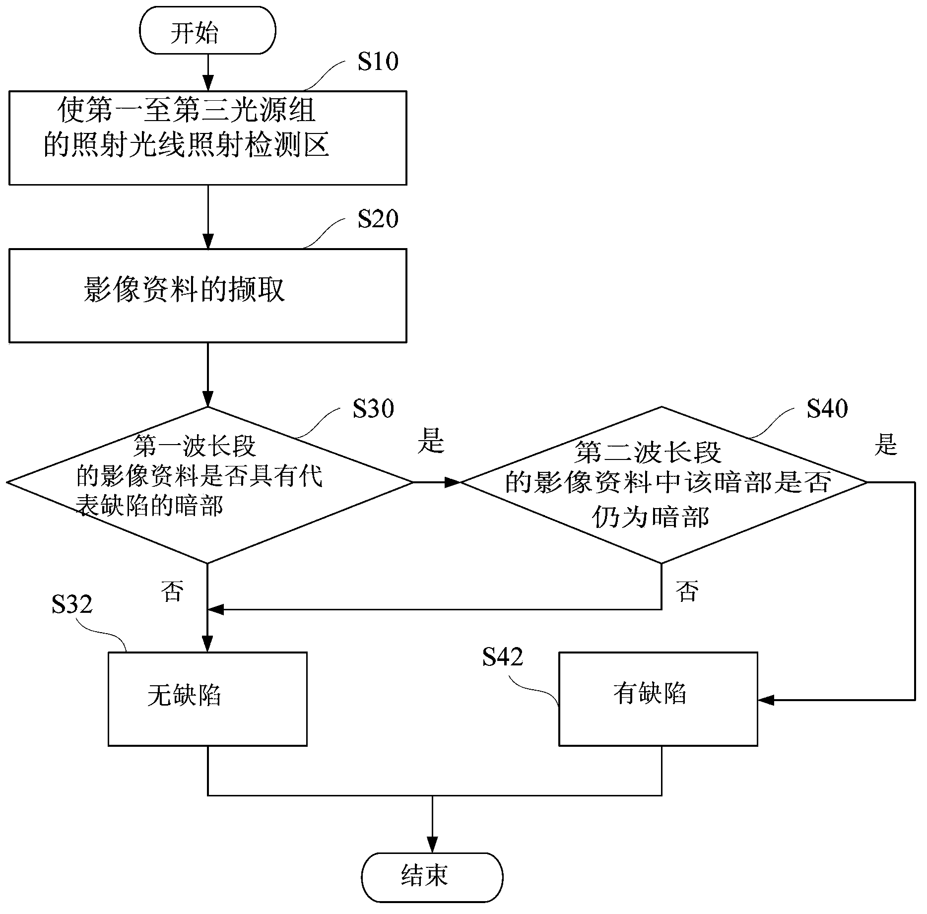
[0054] The present invention uses three sets of light source sets arranged at different illumination angles to illuminate an object to be measured (such as a circuit substrate) and the use of reflected light through different wavelength bands to detect defects and enhance optical The identification of oxidized areas and dust in the image reduces the probability of misjudgment by the imaging system.

[0055] See first figure 1 , Is a system schematic diagram of the detection system in an embodiment of the present invention. The illumination system for optical detection in this embodiment of the present invention is used to provide illumination light to a detection area 500. The illumination system includes a...


PUM

PropertyMeasurementUnit
Angle of incidenceaaaaaaaaaa

Abstract

The invention discloses an illumination system for optical detection, detection system and method using the same. A first illuminating light ray is projected right in the direction to a detection area and two channels of a second light ray are projected biasedly to the detection area. Two channels of a third illuminating light ray illuminate the detection zone at maximum large projection angles. The wavelength of the third illuminating light ray is shorter than those of the first light ray and the second illuminating light ray. A colored linear scanning camera outputs optical image data of different light spectra so that defect can be detected. The mixed images are then cut off by light spectra color frequency to identify oxidation of a circuit board and dust on the circuit board. The third illuminating light ray is further provided with a strengthened ability to identify defects in an optical image, therefore, reducing the error rate of the detection system when it performs detection work.

Description

Technical field [0001] The present invention relates to a related technology of optical detection, in particular to an illumination system for optical detection, a detection system and a detection method using the illumination system. Background technique [0002] The light source system plays a pivotal role in automatic optical inspection (AOI). For example, in the manufacturing process of liquid crystal displays, semiconductor integrated circuit chips and related circuits, they must undergo precise automatic optical inspections. [0003] The detection of wire defects on the circuit board is a part of automatic optical inspection. The traditional detection method is to make the detection light irradiate the object to be tested in the forward direction. Because the wire generally uses metal materials (such as copper materials), it has High reflectivity, judging whether the wire is broken or disconnected by the presence or absence of the reflected light of the irradiated light in t...

Claims


Application Information

Patent Timeline
IPC IPC(8): F21S8/00F21V19/00G01N21/88
CPCF21S8/00F21V19/00G01N21/8806G01N21/9501G01N21/956
Inventor 汪光夏陈辉毓
Owner MACHVISION INC
Why Eureka
Try Eureka