A passively driven electrophoretic electronic paper device and its driving method

An electronic paper and electrophoresis technology, applied in nonlinear optics, instruments, optics, etc., can solve the problems of difficult to meet the production demand of mass products, increase the production process and manufacturing cost, display graphics cannot be displayed, and reduce the processing technology. and device configuration requirements, low manufacturing cost, and the effect of avoiding the influence of displayed content

Active Publication Date: 2017-07-28
DALIAN LONGNING TECH
View PDF6 Cites 0 Cited by
  • Summary
  • Abstract
  • Description
  • Claims
  • Application Information

AI Technical Summary

Problems solved by technology

[0004] The segmented electrophoretic electronic paper flexible circuit board (FPC) or printed circuit board (PCB) in the prior art is used as the substrate, and the display electrodes and display lead electrodes are formed on different surfaces of the substrate and connected through via holes. This type of electrophoretic electronic paper cannot achieve accurate display effects for complex display graphics, and the module processing method generally adopts COB or TAB packaging methods, the cost of raw materials is relatively high, and the processing efficiency is low, such as the realization of 100 segment display devices , if the COB packaging method is adopted, the processing efficiency of a BONGING machine is about 100 pieces per hour, which is difficult to meet the production needs of mass products
There is also an electrophoretic electronic paper in the prior art, which is implemented by first forming display electrodes and display lead electrodes on the substrate. At the same time, in order to avoid the display of the lead electrodes, an insulating layer needs to be covered on the display lead electrodes. The manufacturing process and manufacturing cost are increased, and for some precise graphics, the display accuracy requirements cannot be met by covering the insulating layer. In addition, the setting of the insulating layer will also cause a height difference between the lead electrodes and the display electrodes, making the display graphics Obvious concave-convex feeling

Method used


Image

  • A passively driven electrophoretic electronic paper device and its driving method
  • A passively driven electrophoretic electronic paper device and its driving method
  • A passively driven electrophoretic electronic paper device and its driving method

Examples


Embodiment Construction

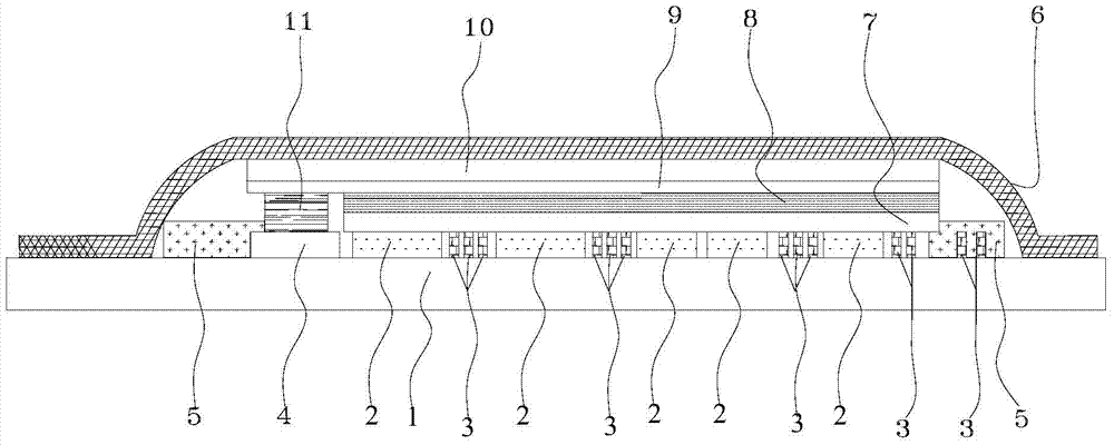
[0024] Such as figure 1 A passively driven electrophoretic electronic paper device shown includes: a display medium layer 8 and an upper substrate 10 and a lower substrate 1 oppositely arranged; a common lead electrode 4 and a display lead electrode 3 are formed on the upper surface of the lower substrate 1 and the display electrode 2; the lower surface of the upper substrate 10 is formed with a common electrode 9; the common electrode 9 is electrically connected to the common lead electrode 4 through the transfer electrode 11; the display electrode 2 is connected to the display lead electrode 3 The display electrode 2 and the display lead electrode 3 are connected to the display medium layer 8 through the glue layer 7, and the display medium layer 8 is accommodated between the glue layer 7 and the common electrode 9; the display An electric field is formed between the electrode 2 and the common electrode 9, which is sufficient to drive the display of the display medium layer ...


PUM


Abstract

The invention discloses a passive driven electrophoresis type electronic paper device and a driving method of the passive driven electrophoresis type electronic paper device. The electronic paper device comprises a display medium layer, and an upper substrate and a lower substrate which are opposite to each other, wherein a public lead electrode, a display lead electrode and a display electrode are formed on the upper surface of the lower substrate; a public electrode is formed on the lower surface of the upper substrate; the public electrode is electrically connected with the public lead electrode by virtue of a transfer printing electrode; the display electrode is connected with the display lead electrode; the display electrode and the display lead electrode are connected with the display medium layer by virtue of an adhesive layer; the display medium layer is arranged between the adhesive layer and the public electrode; an electric field is formed between the display electrode and the public electrode and has the enough powerful to drive the display of the display medium layer. The passive driven electrophoresis type electronic paper device is low in manufacturing cost and high in production efficiency; the application progress and the popularization progress of electronic paper can be greatly facilitated.

Description

technical field [0001] The invention relates to a passively driven electrophoretic electronic paper device and its driving method. Background technique [0002] Electrophoretic electronic paper has attracted widespread attention after its appearance due to its advantages of high contrast, wide viewing angle and low power consumption; the process of displaying information on an electrophoretic display device is to add electrical signals to the electrophoretic display film through the backplane electrode and the common electrode , under the action of an electric field, the positively charged and negatively charged particles will move in different directions to form a black, white or color display state. When the signal is input to the backplane electrode and the common electrode, different potential differences will be formed between the backplane electrode and the common electrode, thereby driving the particles in the electrophoretic display film layer to move, and it can dis...

Claims


Application Information

Patent Timeline
Patent Type & Authority Patents(China)
IPC IPC(8): G02F1/167G09G3/34
CPCG02F1/167G02F1/1676G09G3/3446
Inventor 赵守扬黄晨新
Owner DALIAN LONGNING TECH
Why Eureka
Try Eureka