Manufacturing method for a shield conductor

A technology for shielding conductors and manufacturing methods, applied in cable/conductor manufacturing, conductors, manufacturing tools, etc., can solve the problems of uniformity of metal braid and shielding tube, increase the number of parts, etc., and achieve high electrical contact reliability and parts. The effect of reducing the number of pieces

Inactive Publication Date: 2015-01-14
SUMITOMO WIRING SYST LTD
View PDF9 Cites 4 Cited by
  • Summary
  • Abstract
  • Description
  • Claims
  • Application Information

AI Technical Summary

Problems solved by technology

However, in such a connection method using fastening, it is difficult to make the contact condition between the metal braid and the outer peripheral surface of the shielding tube uniform over the entire circumference, and there is room for improvement in terms of electrical contact reliability.
In addition, due to the use of fastening rings, it was also pointed out that the number of parts increased

Method used


Image

  • Manufacturing method for a shield conductor
  • Manufacturing method for a shield conductor
  • Manufacturing method for a shield conductor

Examples


Embodiment 1

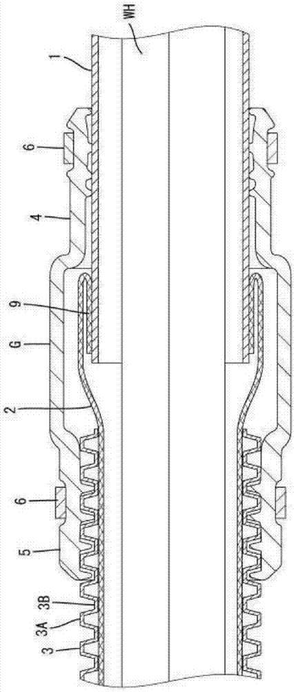
[0027] figure 1 Shown is a wiring harness WH that connects between a battery mounted in the rear compartment and an inverter mounted in the engine room in a hybrid vehicle.

[0028] The wire harness WH is composed of a plurality of electric wires. The wiring of the wire harness WH is partially inserted into the conductive metal shield tube 1 (corresponding to the connection object of the present invention). The shield pipe 1 is made of aluminum or an aluminum alloy, and is placed under the chassis of the vehicle body.

[0029] The end portion of the shielding pipe 1 is connected to the metal braided portion 2 after being introduced into the engine room from under the chassis. The metal braid 2 together with the shielding tube 1 constitutes the shielding conductor of the present invention, and is provided within a predetermined length range until it is connected to the inverter.

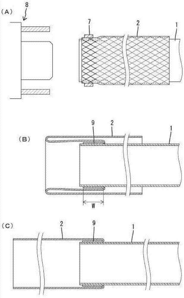
[0030] The metal braid 2 is formed, for example, by braiding copper-based metal wires with tin-...

Embodiment 2

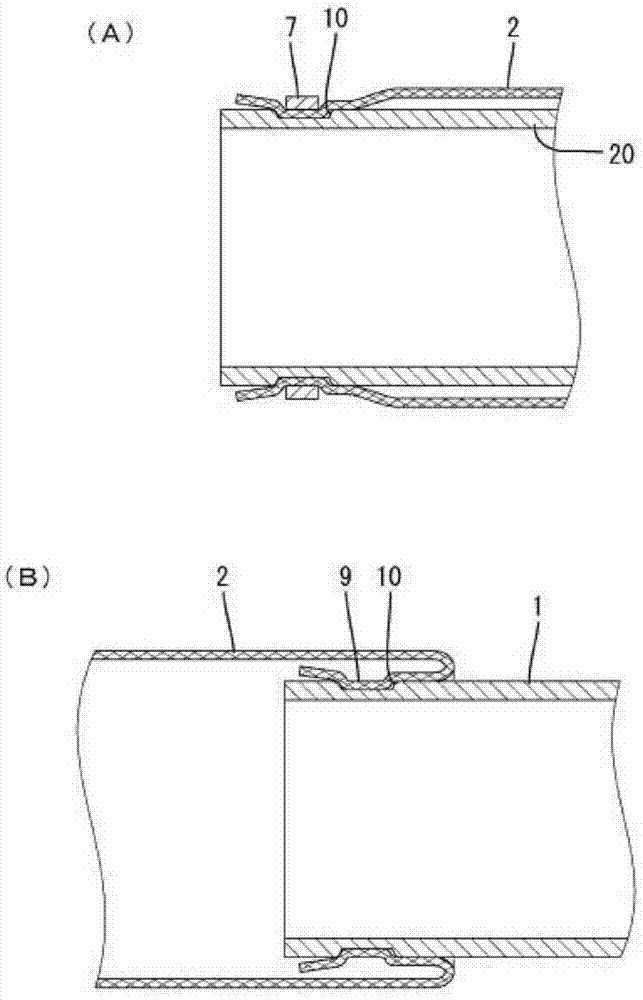
[0043] image 3 (A) (B) shows the manufacturing method of Example 2 of this invention. In Example 2, an annular groove 10 for positioning is recessed on the outer peripheral surface of the end portion of the shielding tube 20 . The annular groove 10 is formed on the entire circumference of the shield tube 20 and is wider than the width of the solder ribbon 7 . In addition, although not shown in detail, the ribbon 7 is cut into a partition groove in the axial direction, and elastically expands / returns with the partition groove as a boundary.

[0044] During ultrasonic welding, after the metal braided portion 2 is covered on the shielding tube 20, the welding ribbon 7 is embedded in the metal braided portion 2 (refer to image 3 (A)). Next, when the welding ribbon 7 is positioned in the annular groove 10 , the welding ribbon 7 can be slightly reduced in diameter by virtue of its own elastic force to exert a fastening force on the metal braided portion 2 . Therefore, the posi...

Embodiment 3

[0048] Figure 4 (A) (B) shows the manufacturing method of Example 3 of this invention. In this embodiment, a pair of flanges 31, 31 are formed on the shield tube 30, and the solder ribbon 7 is positioned between them.

[0049] That is, two flanges 31 , 31 are formed on the entire circumference of the end portion of the shielding tube 30 so as to be spaced apart from each other by a predetermined interval in the longitudinal direction. The two flanges 31 are formed such that the inner peripheral surface side of the shielding tube 30 is recessed and the outer peripheral surface side protrudes. As a result, an annular groove 32 for positioning is formed in a region sandwiched between the two flanges 31 on the outer periphery of the shielding tube 30 .

[0050] In Example 3 thus constituted, the metal braid 2 and the shielding tube 30 can be welded in the same procedure as in Example 2. FIG. In this case, the welding site 9 is also formed in the annular groove 32 along with it...


PUM


Abstract

A method is disclosed for manufacturing a shield conductor by connecting a metallic braid part formed of tubularly braided metallic wire to a part to be connected provided with a tubular part having electrical conductivity. The method includes fitting the metallic braid part to an outer peripheral surface of an end part of the tubular part to form a fitting region; attaching a metallic welding band formed in a ring shape in the fitting region with the metallic braid part fitted to the end part of the tubular part; melting the welding band that is attached in the fitting region; and welding the tubular part to the metallic braid part along a circumferential direction of the tubular part.

Description

technical field [0001] The present invention relates to a method of manufacturing a shielding conductor. Background technique [0002] Conventionally, in hybrid vehicles and electric vehicles, wiring harnesses routed between a battery and an inverter, or between an inverter and a motor are often inserted through metal shielding tubes for wiring. The shielding pipe is arranged in the front-rear direction under the chassis of the vehicle body. The shielding tube has a shielding function for electric wire shielding and a function for protecting electric wires from flying stones and the like. After the shield tube is introduced into the engine room, it is connected to the inverter side through a flexible metal braid, which improves the degree of freedom in the wiring direction of the wiring harness. The metal braid is formed by weaving metal wires into a net shape, and it covers the end of the metal pipe, and generally, it is often connected by fastening with a fastening ring....

Claims


Application Information

Patent Timeline
Patent Type & Authority Applications(China)
IPC IPC(8): H01R43/02
CPCB23K1/0016B23K1/06H01B13/22B23K2001/12B23K20/10H02G3/0666H02G3/0468H02G3/0481H02G3/0691B23K2101/32B23K2101/38B23K2103/12
Inventor 中井洋和大平雄贵
Owner SUMITOMO WIRING SYST LTD
Why Eureka
Try Eureka