Wireless energy transmitting system and harmonic wave eliminating and power adjusting method for wireless energy transmitting system

A technology of harmonic elimination and wireless power transmission, applied in the direction of adjusting electrical variables, electromagnetic wave systems, harmonic reduction devices, etc., can solve the distortion of the coil current at the sending end, reduce system reliability and efficiency, and cannot completely eliminate low-order harmonics And other problems, to achieve the effect of preventing mutual charge and discharge

Active Publication Date: 2015-01-14
SOUTHWEST JIAOTONG UNIV
View PDF3 Cites 1 Cited by
  • Summary
  • Abstract
  • Description
  • Claims
  • Application Information

AI Technical Summary

Problems solved by technology

The existing problems are: 1. Adjust the fundamental effective value of the inverter output voltage through the buck-boost direct-to-direct converter to realize power regulation; while the buck-boost direct-to-direct converter has a complex structure, which increases the system The complexity reduces the reliability and efficiency of the system
2. Limited by the capacity of switching devices, the power of a single high-frequency inverter is limited, which makes it difficult for the output power of the system to meet the requirements of high-power power transmission (such as wireless power transmission for transportation equipment)
Moreover, the high-frequency inverter is usually a two-level single-phase full-bridge inverter, and its output is an alternating voltage with alternating positive and negative levels (rather than a sine wave), which has high harmonic content. Although the subsequent resonant circuit It can eliminate most of the high-order harmonics, but it cannot completely eliminate the low-order harmonics, which will easily distort the coil current at the sending end and affect the transmission performance of the system

Method used


Image

  • Wireless energy transmitting system and harmonic wave eliminating and power adjusting method for wireless energy transmitting system
  • Wireless energy transmitting system and harmonic wave eliminating and power adjusting method for wireless energy transmitting system
  • Wireless energy transmitting system and harmonic wave eliminating and power adjusting method for wireless energy transmitting system

Examples


Embodiment

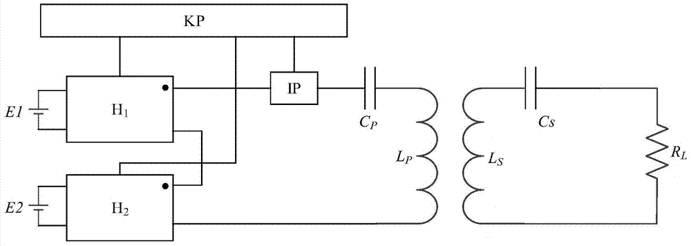
[0045] figure 1 It is shown that a specific embodiment of the present invention is a wireless power transmission system, which is composed of a receiving end and a transmitting end; wherein, the receiving end includes a receiving end coil Ls connected in series, a receiving end compensation capacitor Cs and load R L ; The sending end includes an inverter connected in series, a current sensor IP, a sending end compensation capacitor Cp, and a sending end coil Lp, and the inverter and the current sensor IP are all connected to the controller KP, which is characterized in that:

[0046] The inverter is a cascaded multilevel inverter composed of the output end of the first full-bridge inverter H1 and the output end of the second full-bridge inverter H2 connected in series; and the first full-bridge The input terminal of the inverter H1 is connected to the DC power supply 1 E1, and the input terminal of the second full-bridge inverter H2 is connected to the DC power supply 2 E2; t...


PUM


Abstract

The invention discloses a wireless energy transmitting system and a harmonic wave eliminating and power adjusting method for the wireless energy transmitting system. According to the wireless energy transmitting system, an inverter is a cascade type multi-level inverter formed by cascading the output end of a first full-bridge inverter (H1) and the output end of a second full-bridge inverter (H2). The input end of the first full-bridge inverter (H1) is connected with a first direct-current power source (E1). The input end of the second full-bridge inverter (H2) is connected with a second direct-current power source (E2). The first power source (E1) and the second power source (E2) are isolated from each other, and the amplitudes of the output voltages of the first power source (E1) and the amplitudes of the output voltages of the second power source (E2) are identical. The inverters and a current sensor (IP) are both connected with a controller in the specific mode that the control end of the first full-bridge inverter (H1), the control end of the second full-bridge inverter (H2) and the output end of the current sensor (IP) are all connected with the controller (KP). The wireless energy transmitting system is high in output electric power, low in complexity, high in reliability, and high in efficiency.

Description

technical field [0001] The invention relates to the technical field of wireless energy transmission, in particular to a wireless energy transmission system and a method for eliminating harmonics and power adjustment thereof. Background technique [0002] When the wireless power transmission technology is applied to the power supply of mobile equipment such as rail transit trains and electric vehicles, it overcomes the defects of the traditional wired power transmission technology, such as easy carbon deposition, contact sparks, and troublesome plugging operations. [0003] The main composition and working process of the existing wireless power transmission system are: the rectifier converts the power frequency alternating current into direct current, and under the control of the controller, it is converted into the required voltage by the buck-boost direct-direct converter, and then the high-frequency The inverter converts direct current into high-frequency alternating curre...

Claims


Application Information

Patent Timeline
Patent Type & Authority Applications(China)
IPC IPC(8): H02J17/00H02J3/01G05F1/66H02J50/12
CPCG05F1/66H02J3/01Y02E40/40
Inventor 麦瑞坤李勇陆立文何正友高仕斌
Owner SOUTHWEST JIAOTONG UNIV
Why Eureka
Try Eureka