
Fuel cell system

A fuel cell system and fuel cell technology, applied in the direction of fuel cells, fuel cell additives, solid electrolyte fuel cells, etc., can solve problems such as the degradation of catalyst layer performance and power generation performance, and the reduction of the effective area of ​​platinum catalysts

Active Publication Date: 2015-01-14
TOYOTA JIDOSHA KK
View PDF5 Cites 12 Cited by
  • Summary
  • Abstract
  • Description
  • Claims
  • Application Information

AI Technical Summary

Problems solved by technology

[0003] In such a fuel cell system, when the cell operation is continued in the operating region where the cell voltage becomes the oxidation voltage (approximately 0.7 V to 1.0 V), an oxide film is formed on the surface of the platinum catalyst in the catalyst layer, and the platinum catalyst is present. When the effective area decreases, the performance of the catalyst layer and even the power generation performance decrease

Method used


Image

  • Fuel cell system
  • Fuel cell system
  • Fuel cell system

Examples


Embodiment Construction

[0050] Hereinafter, embodiments of the present invention will be described with reference to the drawings.

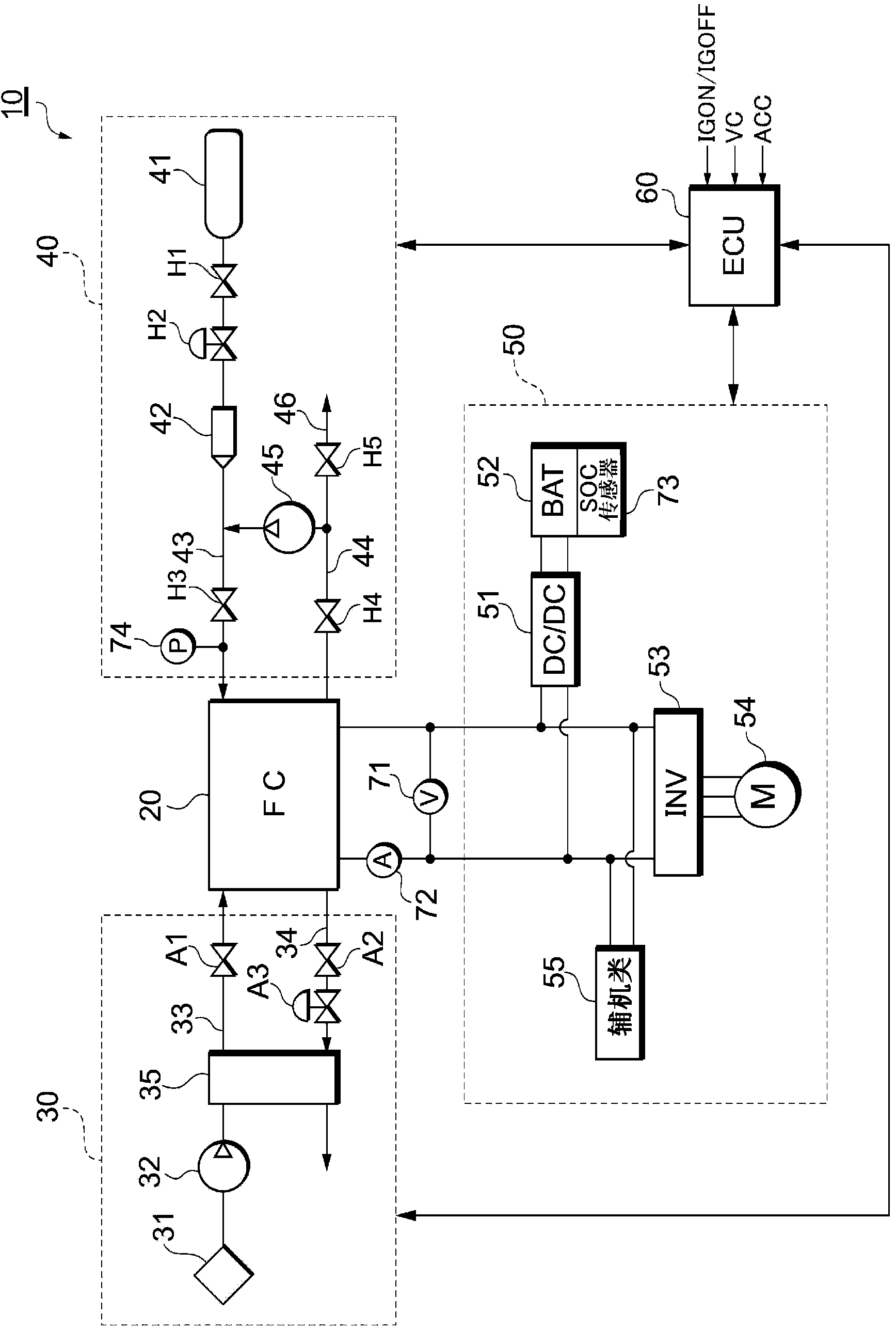
[0051] figure 1 A system configuration of a fuel cell system 10 according to an embodiment of the present invention is shown.

[0052] The fuel cell system 10 functions as an on-vehicle power supply system mounted on a fuel cell vehicle, and includes: a fuel cell stack 20 for generating electricity by receiving a supply of reactant gas (fuel gas, oxidizing gas); An oxidizing gas supply system 30 supplied from the cell stack 20; a fuel gas supply system 40 for supplying hydrogen as a fuel gas to the fuel cell stack 20; an electric power system 50 for controlling charge and discharge of electric power; and unification of the entire system controlled by the controller 60 .

[0053] The fuel cell stack 20 is a solid polymer electrolyte type single cell stack in which a plurality of single cells are stacked in series. In the fuel cell stack 20, the oxidation reaction of t...


PUM


Abstract

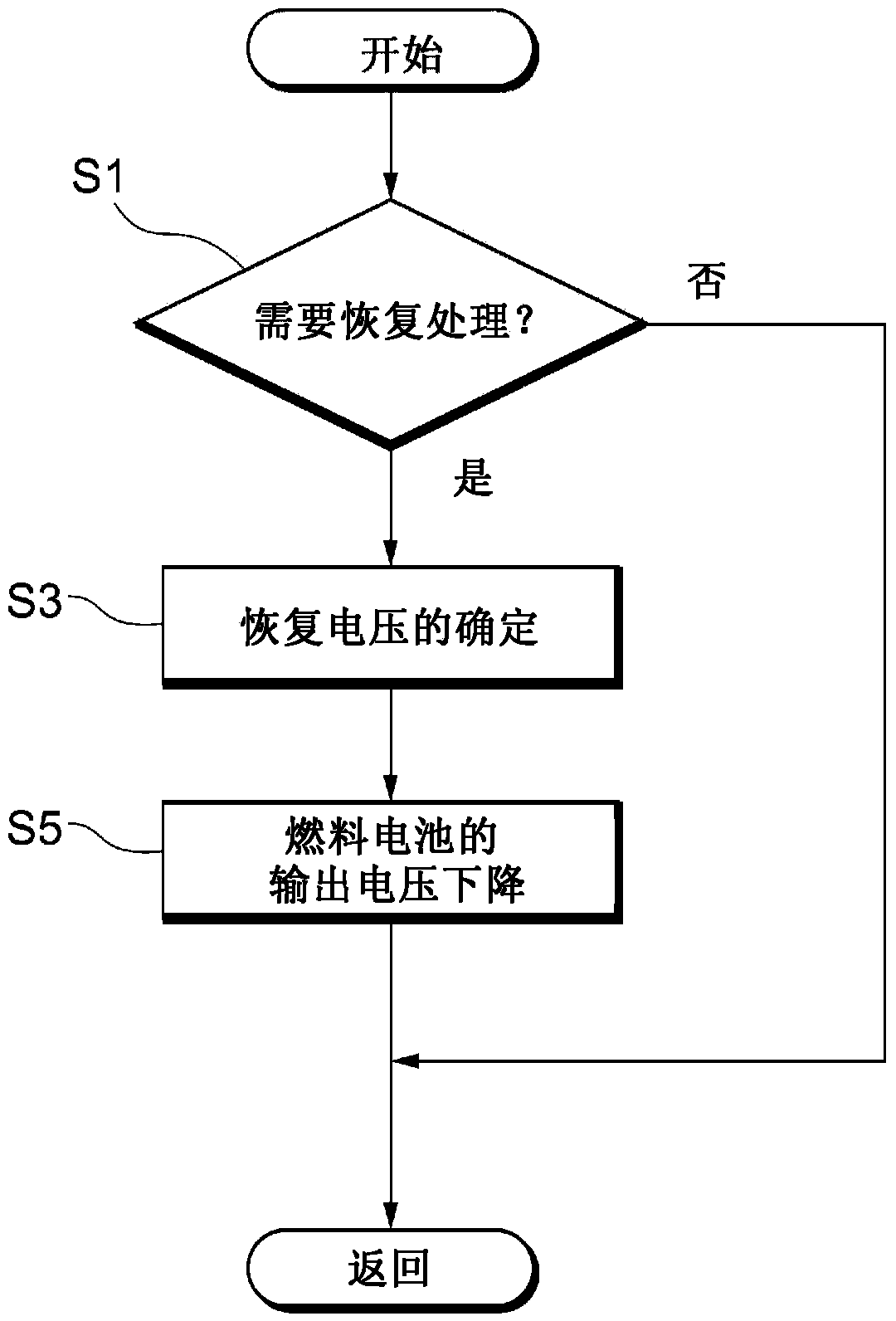
This fuel cell system is provided with a control device for performing catalyst layer performance recovery treatment by decreasing the output voltage of a fuel cell to a predetermined voltage. When determining that an oxide film formed on a catalyst layer during the generation of electricity by the fuel cell contains, in addition to a first oxide film that can be removed by decreasing the output voltage of the fuel cell to a first film removal voltage, a second oxide film that cannot be removed unless the output voltage is decreased to a second film removal voltage lower than the first film removal voltage, the control device estimates the amount of the second oxide film, and when determining that the estimated amount exceeds a predetermined amount (A), performs the performance recovery treatment at a set voltage equal to or less than the second film removal voltage.

Description

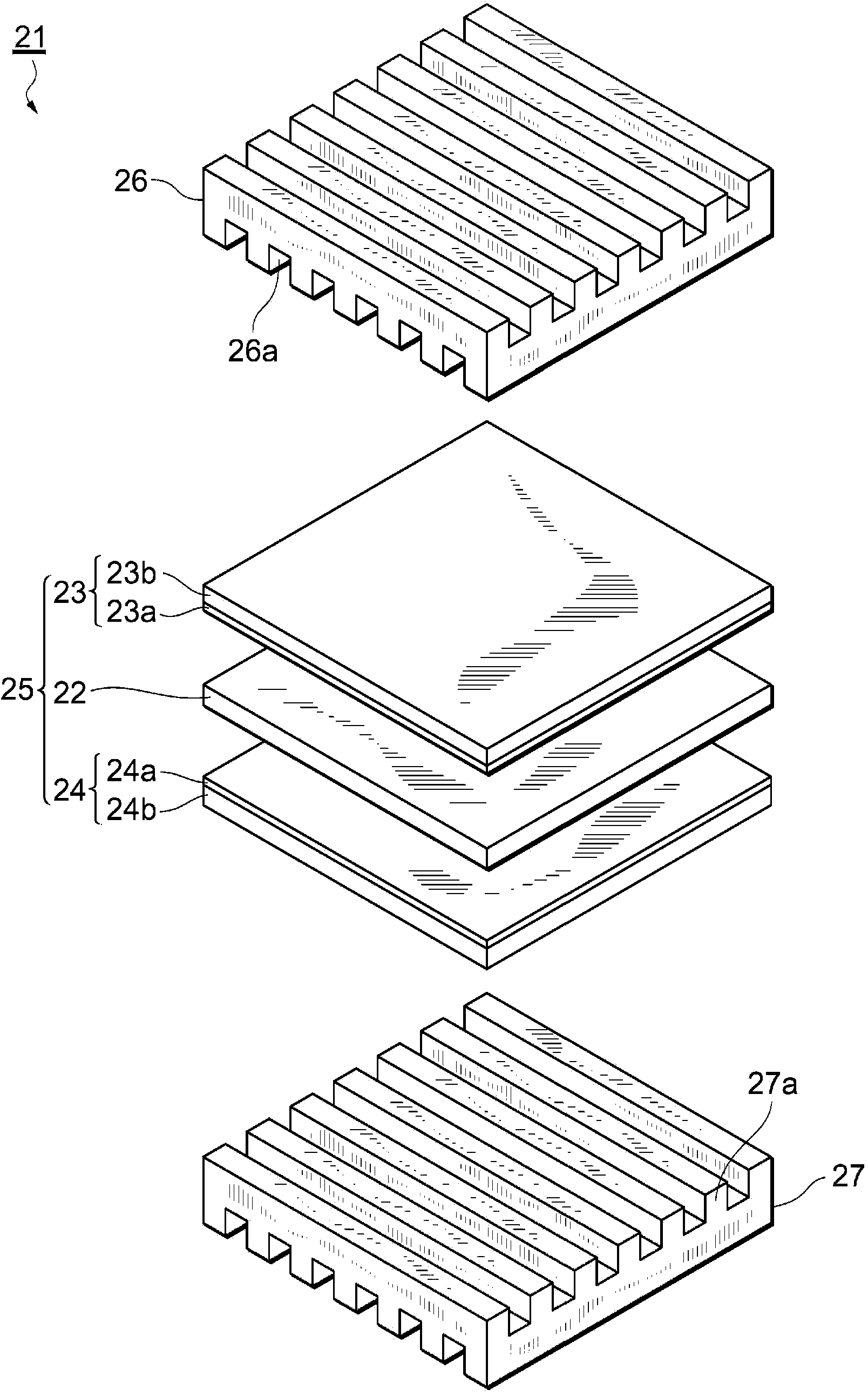
technical field [0001] The present invention relates to a fuel cell system having a catalyst activation function. Background technique [0002] A fuel cell stack is a power generation system that oxidizes fuel through an electrochemical process, thereby directly converting energy released with the oxidation reaction into electrical energy. A fuel cell stack has a membrane electrode assembly in which a polymer electrolyte membrane for selectively transporting hydrogen ions is sandwiched between a pair of electrodes made of a porous material. The pair of electrodes respectively have: a catalyst layer, mainly composed of carbon powder carrying a platinum-based metal catalyst, and connected to the polymer electrolyte membrane; and a gas diffusion layer, formed on the surface of the catalyst layer, and has a ventilation function properties and electronic conductivity. [0003] In such a fuel cell system, when the cell operation is continued in the operating region where the cel...

Claims


Application Information

Patent Timeline
Patent Type & Authority Applications(China)
IPC IPC(8): H01M8/04H01M4/90H01M8/10
CPCH01M2008/1095H01M8/04223H01M8/0488Y02E60/50H01M8/04873H01M8/04671H01M8/04225H01M8/04302H01M8/04238H01M8/04865
Inventor 池田耕太郎松末真明井上侑美
Owner TOYOTA JIDOSHA KK
Learn More