Two ends flaring forming technique of cylindrical barrels

A cylindrical barrel, the technology of molding process, applied in the direction of bicycle accessories, transportation and packaging, etc.

Inactive Publication Date: 2015-01-21
CHONGQING JINLUN IND
View PDF0 Cites 1 Cited by
  • Summary
  • Abstract
  • Description
  • Claims
  • Application Information

AI Technical Summary

Problems solved by technology

[0003] The present invention provides a process of flaring at both ends of a cylindrical cylinder to solve the problems of complex processing technology and large flaring error of the existing cylindrical cylinder

Method used


Image

  • Two ends flaring forming technique of cylindrical barrels
  • Two ends flaring forming technique of cylindrical barrels
  • Two ends flaring forming technique of cylindrical barrels

Examples


Embodiment Construction

[0017] In this embodiment, the machining process of the inner cylinder of a motorcycle muffler is taken as an example.

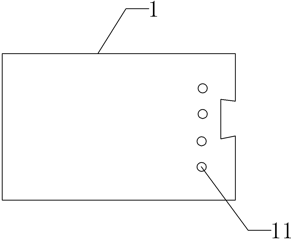
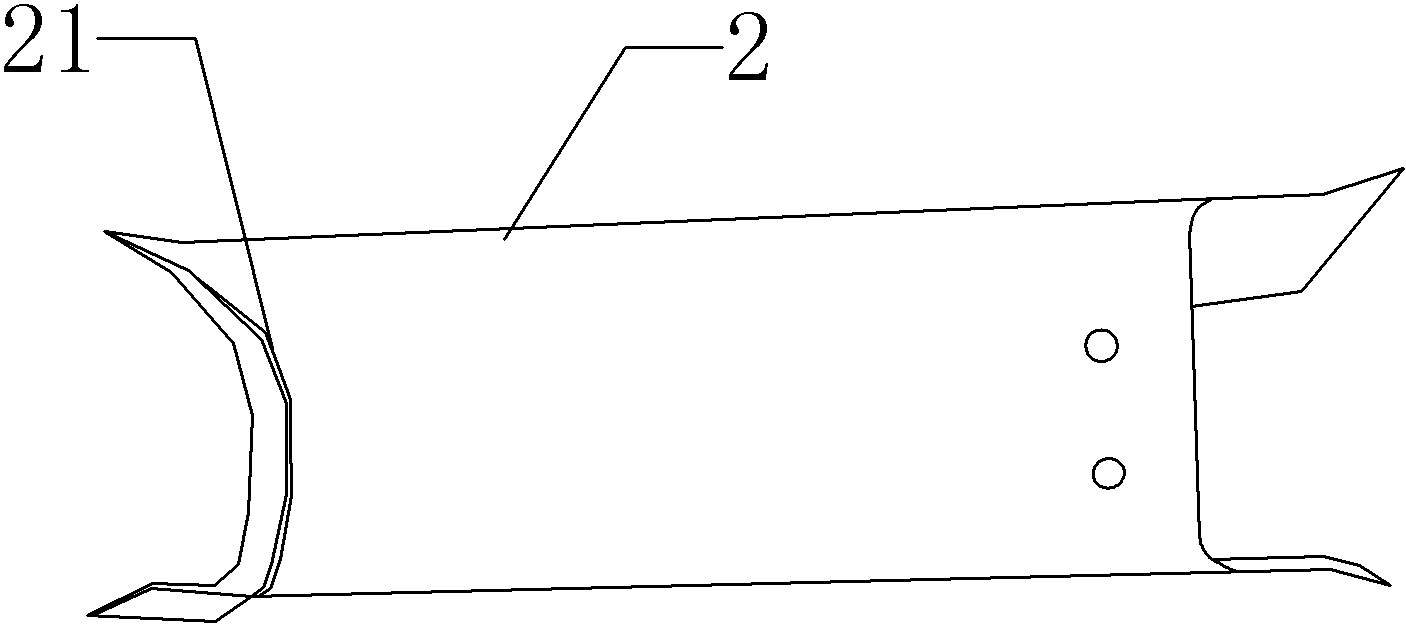
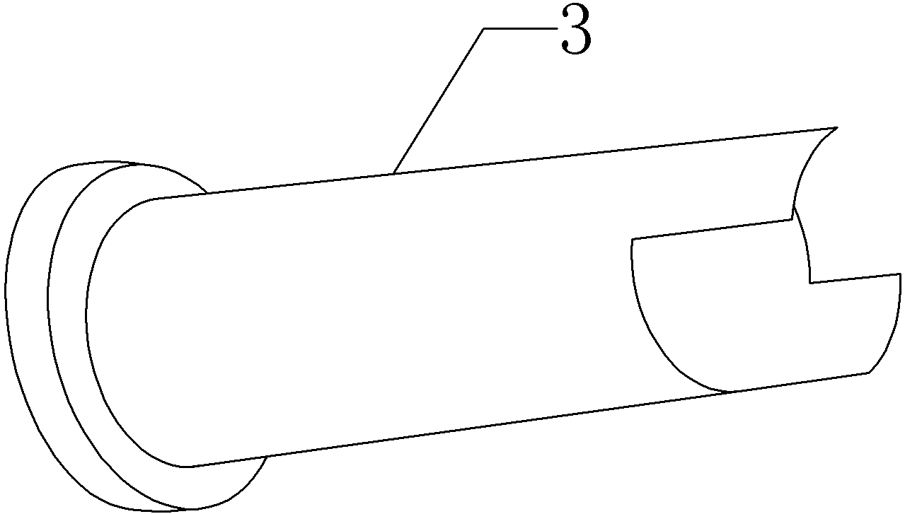
[0018] First, the raw material is directly expanded into the sheet material 1, and holes 11 are punched on the sheet material. The use of the sheet material will reduce the stretching deformation of the raw material during molding. Then hit U again to make the sheet material 1 become a U-shaped body 2. When hitting the U, make the end of the sheet material face down to form a flat surface at both ends. At the same time as the flat surface, the stepped bosses 21 at both ends are formed into Good, therefore, this reduces many processes such as first rolling, then flattening, and expanding both ends; finally, putting in the rolling mold, adding the mandrel and then rolling, welding straight seams after rolling, forming a cylindrical shape Cylinder 3.

[0019] In this embodiment, one end of the U-shaped body has a boss, the other end has two legs, and the arc of the...


PUM


Abstract

The invention provides a two ends flaring forming technique of cylindrical barrels and aims to solve the problems of the existing cylindrical barrels of complex processing techniques and large flaring error. The scheme includes that the two ends flaring forming technique is characterized by including the following steps: (1) unfolding raw materials to be sheet materials according to the shapes of workpieces; (2) making the sheet materials to be U-shaped bodies, forming the plane where two ends of each cylindrical barrel are located, and forming bosses of steps; (3) putting a curling die and a mandrel, and then conducting curling; (4) welding straight lines.

Description

technical field [0001] The invention relates to a processing technology of a cylinder body, in particular to a process for forming both ends of a cylindrical cylinder body by flaring. Background technique [0002] The main function of the cylinder is to provide a relatively stable working environment for the mechanism, instrument or equipment arranged inside it. The cylinder is divided into a cylindrical cylinder and a spherical cylinder. In order to facilitate installation and connection, it is usually necessary to flaring the cylindrical barrel, that is, to form stepped bosses at both ends of the cylindrical barrel. The processing technology of the existing cylindrical cylinder comprises the following steps: blanking and punching; punching into a U-shaped body; rounding; welding straight seam; flaring; double incision; forming; The above-mentioned process has the following problems: 1. The processing procedure is cumbersome, which takes up more equipment and human reso...

Claims


Application Information

Patent Timeline
Patent Type & Authority Applications(China)
IPC IPC(8): B21D53/86
CPCB21D53/86B21D41/02
Inventor 李胜
Owner CHONGQING JINLUN IND
Why Eureka
Try Eureka