
Non-planar-long-and-thin-profile-machining-oriented self-adaptive linkage clamping device and method

A clamping device and type material technology, applied in positioning devices, metal processing equipment, metal processing machinery parts, etc., can solve the problems of high labor intensity of workers, deformation of workpieces, affecting processing efficiency, etc., to reduce labor intensity of workers, ensure The effect of machining accuracy and improving machining efficiency

Inactive Publication Date: 2015-01-21
XI AN JIAOTONG UNIV
View PDF9 Cites 17 Cited by
  • Summary
  • Abstract
  • Description
  • Claims
  • Application Information

AI Technical Summary

Problems solved by technology

However, due to the variable wall thickness of the upper and lower edges (gradually changing between 2 and 3 mm) during finishing, the vacuum adsorption effect is not ideal, so the traditional bolt clamping method is used to clamp the workpiece (the length of the stringer is 10 to 20 meters) There are more than 10 sets of machine tool calipers used on special milling machines, and two bolt clamps are installed on one set of calipers, which takes a long time for clamping). It is cumbersome, which seriously affects the processing efficiency, and the uneven clamping force during the clamping process will easily cause the deformation of the workpiece, resulting in low processing accuracy of the workpiece, or even scrapped

Method used


Image

  • Non-planar-long-and-thin-profile-machining-oriented self-adaptive linkage clamping device and method
  • Non-planar-long-and-thin-profile-machining-oriented self-adaptive linkage clamping device and method
  • Non-planar-long-and-thin-profile-machining-oriented self-adaptive linkage clamping device and method

Examples


Embodiment Construction

[0023] The present invention will be further described below in conjunction with the accompanying drawings.

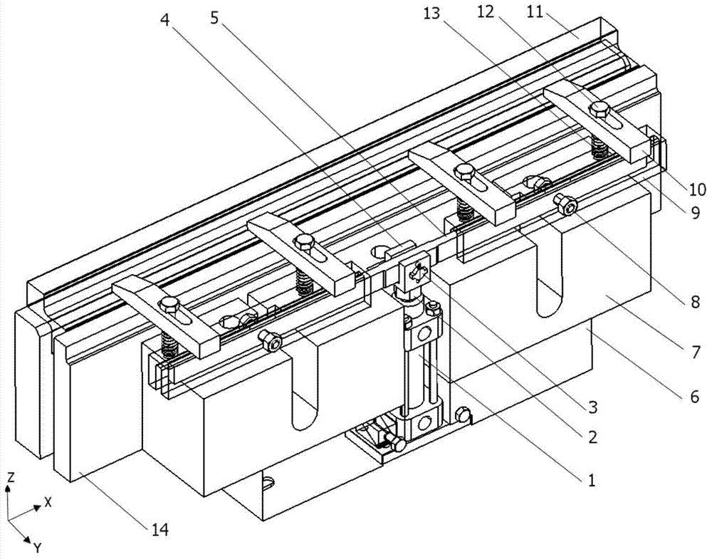
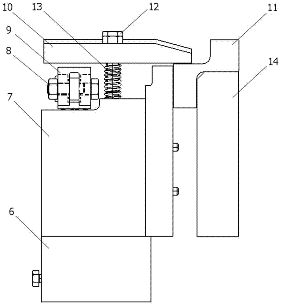
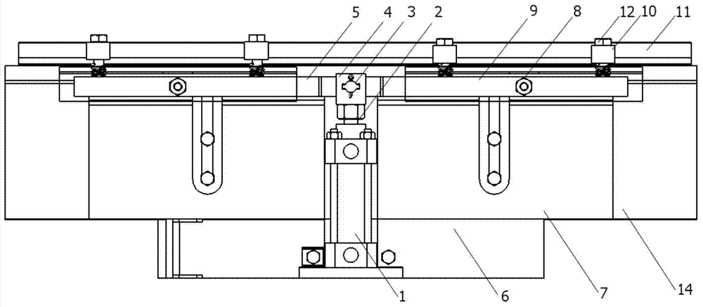
[0024] see figure 1 , figure 2 , image 3 and Figure 4 , an adaptive linkage clamping device for processing non-planar slender materials includes a tooling block 14, one side of the tooling block 14 is provided with a machine tool caliper base 6, and two auxiliary grooves are arranged on the machine tool caliper base 6 Limiting block 7, the tops of the two auxiliary groove limiting blocks 7 are provided with four briquetting blocks 10 fixed by limit bolts 12, and the four briquetting blocks 10 are symmetrically arranged on the two auxiliary groove limiting blocks 7, The briquetting block 10 is provided with a sliding through hole, and one end extends to the top of the tooling block 14, the limit bolt 12 is provided with a spring 13, and the drive cylinder 1 is arranged between the two auxiliary groove limit blocks 7, and the drive cylinder 1 passes through the two...


PUM


Abstract

The invention discloses a non-planar-long-and-thin-profile-machining-oriented self-adaptive linkage clamping device and method. One side of a tool block is provided with a machine tool caliber base. Two auxiliary groove limiting blocks are arranged on the machine tool caliber base. The top ends of the two auxiliary groove limiting blocks are provided with pressing blocks fixed through limiting bolts respectively. The pressing blocks are provided with sliding through holes. One ends of the pressing blocks stretch to the position above the tool block. The limiting bolts are provided with springs. A drive cylinder is arranged between the two auxiliary groove limiting blocks. The top of the drive cylinder is connected with a push rod with a main groove, a rotating lever is arranged in the main groove, and the main groove is provided with a limiting pin shaft penetrating through the main groove and connected with the rotating lever and capable of controlling the inclination angle of the rotating lever. According to the non-planar-long-and-thin-profile-machining-oriented self-adaptive linkage clamping device and method, the inclination angle of the rotating lever can be changed by rotating the limiting pin shaft, it is avoided that mechanical pressing plate clamping is originally conducted by tightening the bolts manually, the labor intensity of workers can be lowered, the auxiliary time is saved effectively, and the machining efficiency is improved.

Description

technical field [0001] The invention belongs to the field of fixtures, and in particular relates to an adaptive linkage clamping device and method for processing non-planar slender materials. Background technique [0002] The long truss parts are used for the wings and fuselage of the aircraft, which are slender parts; the rib parts have complex structures and obvious non-planar surface features, and are used for the empennage and wings of the aircraft. At present, when processing slender aerospace structural parts, vacuum adsorption is often used in the vertical direction, and the hydraulic calipers that come with the milling machine are used for clamping in the horizontal direction. However, due to the variable wall thickness of the upper and lower edges (gradually changing between 2 and 3 mm) during finishing, the vacuum adsorption effect is not ideal, so the traditional bolt clamping method is used to clamp the workpiece (the length of the stringer is 10 to 20 meters) T...

Claims


Application Information

Patent Timeline
IPC IPC(8): B23Q3/00
CPCB23Q3/064
Inventor 赵万华张俊庞博张星王超
Owner XI AN JIAOTONG UNIV
Learn More