Double-sided array push-broom three-dimensional mapping imaging method and imaging system

A technology of stereo surveying and imaging system, applied in the field of imaging system, which can solve the problems of reduced accuracy and low attitude measurement rate

Inactive Publication Date: 2016-07-27
CHANGCHUN INST OF OPTICS FINE MECHANICS & PHYSICS CHINESE ACAD OF SCI
View PDF0 Cites 0 Cited by
  • Summary
  • Abstract
  • Description
  • Claims
  • Application Information

AI Technical Summary

Problems solved by technology

[0005] In order to solve the problem that the existing three-line array push-broom imaging requires corresponding attitude parameters for each row of images, resulting in low attitude measurement rate and greatly reduced accuracy, the present invention provides a double-sided array push-broom three-dimensional surveying and mapping imaging method and imaging system

Method used


Image

  • Double-sided array push-broom three-dimensional mapping imaging method and imaging system
  • Double-sided array push-broom three-dimensional mapping imaging method and imaging system
  • Double-sided array push-broom three-dimensional mapping imaging method and imaging system

Examples


specific Embodiment approach 1

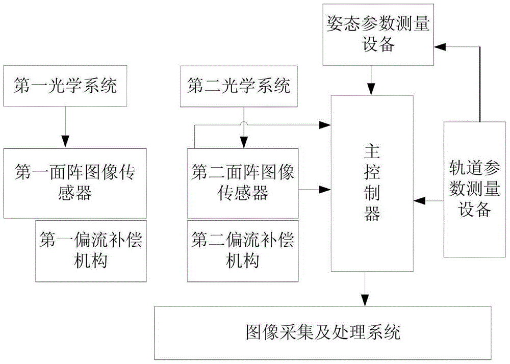
[0032] Specific implementation mode 1. Combination figure 1 Description of this embodiment, the double-sided array push-broom stereo surveying and mapping imaging system includes a main controller, a first optical system, a second optical system, a first area array CCD image sensor connected to the main controller, and a second area array CCD image sensor. Sensors, track parameter measurement equipment, attitude parameter measurement equipment, and image acquisition and processing systems,

[0033] The GPS receiver is used as a reference clock source in the orbital parameter measuring equipment to provide high-precision hardware second pulse signal and GPS whole second time corresponding to the second pulse for the main controller and the attitude parameter measuring equipment, so that each part is at the same time work together under the system. The attitude parameter measuring device provides attitude measurement parameter information for the main controller, and the orbit ...

specific Embodiment approach 2

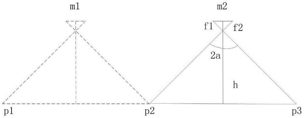
[0037] Specific embodiment two, combine figure 2 This embodiment is described. This embodiment is an imaging method based on the double-sided array push-broom stereo surveying and mapping imaging system described in Embodiment 1. This method is implemented by the following process:

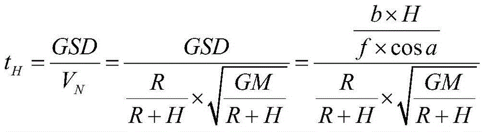
[0038] First, the average velocity Vg of the satellite is calculated according to the following formula:

[0039] V g = GM R + H

[0040]In the formula, G is the gravitational constant, M is the mass of the earth, R is the average radius of the earth, and H is the average altitude of the aircraft from the ground;

[0041] Calculate the average velocity V of the sub-satellite point N (ground speed):

[0042] V N = V g R R ...


PUM


Abstract

The invention discloses a double-area array push-broom three-dimensional surveying and mapping method and a double-area array push-broom three-dimensional surveying and mapping system, and relates to an imaging system, solving the problems that if the existing three-wire array push-broom imaging is adopted, corresponding posture parameters are required for each row of images, and thus the posture measurement velocity is low and the precision is lowered greatly. When the double-sided array push-broom three-dimensional surveying and imaging is carried out, each image meets the central projection principle, and only a group of posture parameters are required for each image, so that the requirement for the posture upgrade rate is lowered; the push-broom three-dimensional surveying and imaging with high base-height ratio is realized by utilizing the double-area array imaging device; the row cycle is set according to the height of a track and the pixel size of a plane array sensor; the maximal frame cycle can be obtained according to the row cycle and the number of columns of the area array sensor; the best frame cycle is calculated according to the height of the track and the included angle of the double-area array optical system; the operation mode of an area array imaging device with high resolution ratio and the included angle of the double-area array optical system are defined.

Description

technical field [0001] The invention relates to an imaging system, in particular to a double-sided array push-broom stereo surveying and mapping imaging system. Background technique [0002] Satellites with stereo mapping or elevation measurement capabilities are called surveying and mapping satellites, whose mission is to conduct stereo observation and obtain the geometric and physical properties of ground targets. Spatial position information is the basic geometric attribute of ground targets, and it is widely used in military and civilian fields. The series of surveying and mapping satellites include high-resolution optical three-dimensional surveying and mapping satellites, interferometric radar satellites, and gravity satellites. High-resolution surveying and mapping satellites using optical sensors are the main data source for current surveying and mapping applications. Good realization and rapid development. [0003] With the development of photogrammetry technology...

Claims


Application Information

Patent Timeline
Patent Type & Authority Patents(China)
IPC IPC(8): G01C11/00
CPCG01C11/00G01C11/02
Inventor 余达刘金国郭永飞徐东孔德柱李嘉张琨
Owner CHANGCHUN INST OF OPTICS FINE MECHANICS & PHYSICS CHINESE ACAD OF SCI
Why Eureka
Try Eureka