
Time synchronization method and system of LMCCD camera

A time synchronization and camera technology, which is applied in the parts of TV systems, TVs, measuring devices, etc., can solve the problems of low positioning accuracy of surveying and mapping images, inability to meet high time accuracy, positioning errors, etc.

Inactive Publication Date: 2015-01-21
CHANGCHUN INST OF OPTICS FINE MECHANICS & PHYSICS CHINESE ACAD OF SCI
View PDF5 Cites 14 Cited by
  • Summary
  • Abstract
  • Description
  • Claims
  • Application Information

AI Technical Summary

Problems solved by technology

[0005] The present invention provides a time synchronization method and a synchronization system for LMCCD cameras to solve the problems of positioning errors in push-broom imaging of existing stereoscopic mapping cameras, which lead to low positioning accuracy of surveying and mapping images, and cannot meet the requirements of high time accuracy.

Method used


Image

  • Time synchronization method and system of LMCCD camera
  • Time synchronization method and system of LMCCD camera
  • Time synchronization method and system of LMCCD camera

Examples


specific Embodiment approach 1

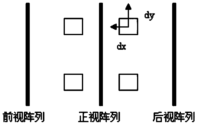
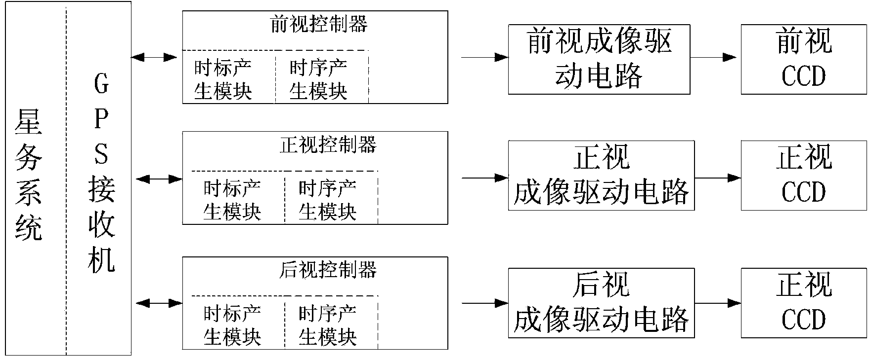
[0039] Specific implementation mode 1. Combination figure 2 Illustrate this embodiment, the time synchronization method of LMCCD camera, this method realizes based on following system: Combine figure 2 , the system includes three linear array CCDs and four area array CCDs. In order to achieve large base height ratio imaging, the front-view and rear-view linear array CCDs each use an optical lens, and the front-view linear array CCD and the four-piece area array CCD share an optical lens.

[0040] The GPS receiver provides the second pulse signal and time information for the front-sight, rear-sight and front-sight controllers, and builds a time synchronization system inside the three controllers to generate time scales. The star system communicates with the front-view, rear-view and front-view controllers to control the imaging of the three cameras; the front-view, rear-view and front-view controllers output timing sequences according to the instructions of the star service ...


PUM


Abstract

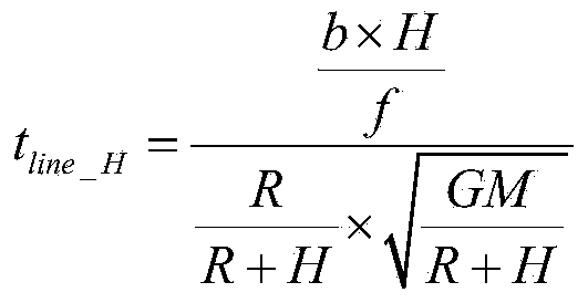
The invention provides a time synchronization method and system of an LMCCD (line matrix CCD) camera, and relates to a time synchronization system. The time synchronization method and system are used for solving the problems that an existing stereoscopic plotting camera in scanning imaging generates positioning errors so as to cause that the positioning accuracy of a plotting image is low, the requirement on high time accuracy cannot be satisfied and the like. According to the time synchronization system, a time scale generation function module and a sensor timing sequence generation module are integrated in a same chip so as to shorten time delay in obtainment of a time scale and uncertain time of the time delay; a pure hardware working mode triggered by a counter is adopted by the time scale generation function module, so that additional time errors caused by adopting a software mode are avoided; timing deviations caused by frequency drifting of crystals are decreased by adopting a self-correcting working mode; the line period of a linear array CCD and the frame period of an area array CCD are calculated according to the height of a track, a pixel size, a principal distance and an intersection angle; and adjustment strategies of the frame period of the area array CCD are stipulated so as to ensure that camera shooting can be carried out by the area array CCD at an oriented moment while the synchronization of the area array CCD and the linear array CCD is maintained.

Description

technical field [0001] The invention relates to a time synchronization system, in particular to a time synchronization system of an LMCCD camera. Background technique [0002] With the development of photogrammetry technology, transmission-type optical stereoscopic mapping satellites can overcome the short orbital life of returnable satellites due to the limitation of the number of films they carry due to their long-term in-orbit operation and the ability to quickly obtain three-dimensional geographic information. The lack of timeliness of information and the inability to directly form digital images have gradually become the mainstream of photogrammetry satellite development. Transmission-type three-line array optical imaging and photogrammetry belong to dynamic photography. The satellite takes pictures of the same target multiple times from different angles of view, and the three-dimensional spatial position information of the target can be determined through post-processi...

Claims


Application Information

Patent Timeline
Patent Type & Authority Applications(China)
IPC IPC(8): G01C11/00
CPCG01C11/025H04N23/66
Inventor 余达刘金国周怀得郭疆陈佳豫赵莹孔德柱
Owner CHANGCHUN INST OF OPTICS FINE MECHANICS & PHYSICS CHINESE ACAD OF SCI
Learn More