Sampling and counting mechanism for diaphragm gas meter
A membrane gas meter and counting mechanism technology, which is applied to volume measurement, measuring devices, instruments, etc., can solve the problems of weak anti-magnetic interference ability and miscount hidden dangers, and achieve good anti-jitter, accurate sampling and counting, and reduce production costs. Effect
- Summary
- Abstract
- Description
- Claims
- Application Information
AI Technical Summary
Problems solved by technology
Method used
Image
Examples
Embodiment 1
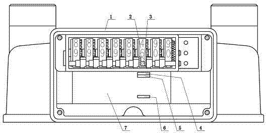
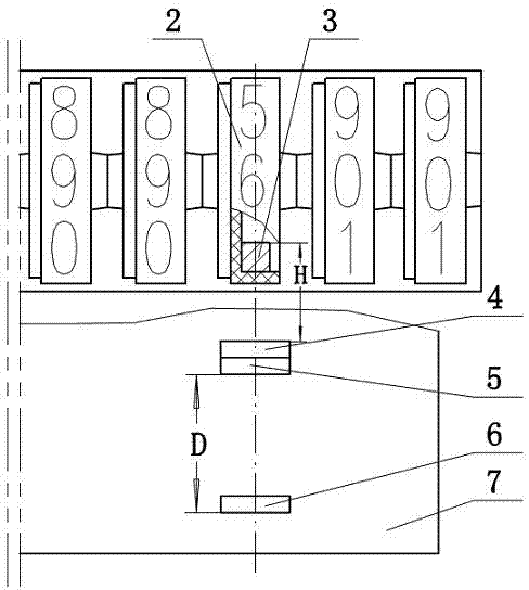
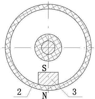
[0018] Such as figure 1 and 2 As shown, a membrane gas meter sampling and counting mechanism includes a gas meter upper casing 1, a character wheel assembly installed in the gas meter upper casing 1, and a control circuit board 7 arranged below the character wheel assembly. The character wheel assembly has eight number wheels 2 coaxially connected in series, and the third one from the right end is the ones digit wheel. The number wheels 2 in the embodiment of this specification are all described with the ones digit wheel as an example. The number wheel 2 is provided with several magnetic steels 3 . The control circuit board 7 is provided with a sampling sensor I4 and a sampling sensor II5. The sampling sensor I4 and the sampling sensor II5 are Hall elements, and the two sampling sensors are close to each other and arranged in the diameter direction of the digital wheel 2 . In order to meet the anti-shake, there is a certain difference in the sensitivity of the two sampling ...
Embodiment 2
[0023] Figure 4 A schematic diagram of installing two magnets 3 for the number wheel 2. The two magnets 3 are symmetrically distributed with the central axis of the number wheel 2 as the axis of symmetry. The N pole of one magnetic steel 3 is connected with the rim of the number wheel 2, and the S pole of the other magnetic steel 3 is connected with the rim of the number wheel 2. The rotation of the digital wheel 2 drives the rotation of the magnetic steel 3, and the rotation of the magnetic steel 3 for one revolution is as follows:
[0024] output port
Embodiment 3
[0026] Figure 5 Schematic diagram of installing four magnets 3 for the number wheel 2. Four magnetic steels 3 are evenly distributed along the rim of the number wheel 2. Two magnetic steels 3 distributed symmetrically with the axis of the digital wheel 2 as a symmetrical axis form a group. In the vertical group, the N pole of each magnetic steel 3 is connected to the rim of the digital wheel 2. In the horizontal group, The S pole of each magnetic steel 3 is connected with the rim of the number wheel 2 . The digital wheel 2 drives the magnetic steel 3 to rotate, and the magnetic steel 3 rotates once. The sampling sensor Ⅰ4 and the sampling sensor Ⅱ5 sense the output pulse generation timing table as follows:
[0027]
[0028]
PUM
 Abstract
Description
Claims
Application Information
 - R&D
- Intellectual Property
- Life Sciences
- Materials
- Tech Scout
- Unparalleled Data Quality
- Higher Quality Content
- 60% Fewer Hallucinations
Browse by: Latest US Patents, China's latest patents, Technical Efficacy Thesaurus, Application Domain, Technology Topic, Popular Technical Reports.
© 2025 PatSnap. All rights reserved.Legal|Privacy policy|Modern Slavery Act Transparency Statement|Sitemap|About US| Contact US: help@patsnap.com


