
PEA space charge measurement system and method under full-size high-voltage direct current cable temperature control gradient

A space charge and DC cable technology, applied in the direction of measuring devices, measuring electrical variables, instruments, etc., can solve problems such as difficult to ensure measurement and inconvenient measurement, and achieve measurement sensitivity and accuracy, excellent piezoelectric performance, and high resolution and the effect of measurement accuracy

Active Publication Date: 2015-01-21
ELECTRIC POWER RESEARCH INSTITUTE, CHINA SOUTHERN POWER GRID CO LTD
View PDF10 Cites 13 Cited by
  • Summary
  • Abstract
  • Description
  • Claims
  • Application Information

AI Technical Summary

Problems solved by technology

[0007] Finally, the metal electrode in the existing coaxial model cable PEA measurement system is processed into a fan shape to fit the cable with a cylindrical outer surface. This electrode design is only suitable for a single-sized cable sample. Once the outer diameter of the cable changes Changes, the original electrode system will no longer be applicable, which will bring great inconvenience to the measurement
For another flat electrode design, when measuring large-sized cables, it will be difficult to ensure that the measurement is carried out at the same fixed point due to the temperature change caused by the change of the test load and the influence of the self-weight of the PEA measurement device.

Method used


Image

  • PEA space charge measurement system and method under full-size high-voltage direct current cable temperature control gradient
  • PEA space charge measurement system and method under full-size high-voltage direct current cable temperature control gradient
  • PEA space charge measurement system and method under full-size high-voltage direct current cable temperature control gradient

Examples


Embodiment 4

[0097] Such as Figure 5 Shown is the flow chart of the PEA space charge measurement method of the embodiment of the present invention, including the following steps:

[0098] S1 Remove the cable outer sheath of the test cable measurement area to expose the outer semiconductive layer, then fix the test cable measurement area between the upper and lower electrodes, and keep the outer semiconductive layer in good contact with the upper and lower electrode surfaces;

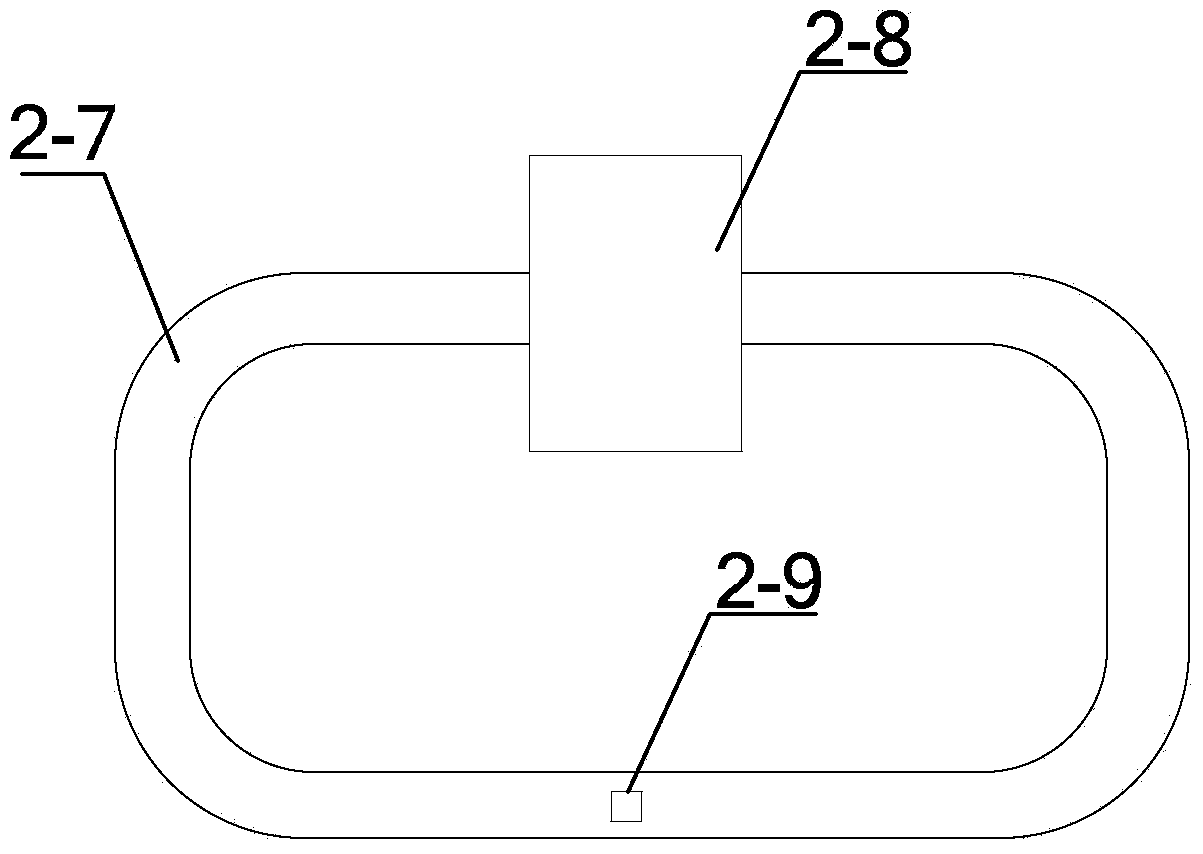
[0099] S2 connects the test cable and the simulated cable respectively to form a closed loop;

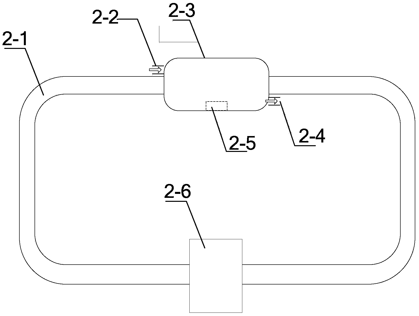
[0100] S3 Set up a DC cable insulation layer temperature gradient control device surrounding the outer semiconducting layer of the cable in the test cable measurement area;

[0101] S4 adjusts the temperature of the DC cable core conductor, so that the test cable core conductor rises to the specified working temperature within the specified heating time;

[0102] S5 adjusts the temperature and humidity in the closed spa...


PUM


Abstract

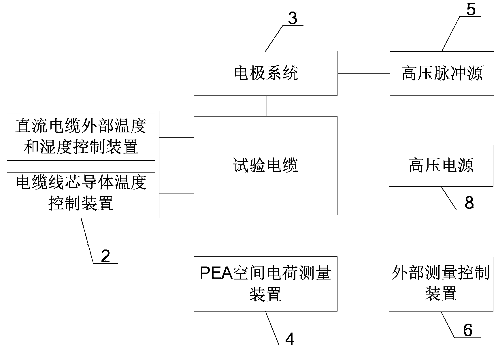
The invention discloses a PEA space charge measurement system under a full-size high-voltage direct current cable temperature control gradient. The system comprises a direct current cable insulation layer temperature gradient control device (2), an electrode system (3), a PEA space charge measurement device (4) and an external measurement control device (6). The direct current cable insulation layer temperature gradient control device is provided with a closed space surrounding a test cable, the electrode system (3) is connected to the test cable inside the closed space and is connected with a high-voltage impulse source (5) outside the closed space through a wire, the PEA space charge measurement device (4) is connected to the electrode system (3), and the external measurement control device (6) is located outside the closed space and is connected with the PEA space charge measurement device (4). The PEA space charge measurement system and method are used for space charge measurement of an insulation layer of a full-size high-voltage direct current cable under the temperature control gradient in the research and development test period, the prequalification test period, the load cycle test period and the long-term aging test period, and the high resolution ratio and measurement precision can be achieved.

Description

technical field [0001] The invention relates to a PEA (electroacoustic pulse method) space charge measurement system under the temperature gradient control of a full-scale high-voltage direct-current cable. The system is based on the PEA measurement method and can be used for a full-scale high-voltage direct-current cable (engineering application level, such as a voltage level of 160kV) or above, insulation thickness between 10mm and 20mm) space charge measurement of extruded insulation layers (such as cross-linked polyethylene XLPE) under controlled temperature gradients during development tests, pre-qualification tests, load cycle tests and long-term aging tests. The present invention also relates to a method for measuring the space charge of a full-scale high-voltage direct current cable under a temperature gradient controlled by PEA (pulse electroacoustic method) using the above-mentioned system. Background technique [0002] In recent years, HVDC transmission technology...

Claims


Application Information

Patent Timeline
Patent Type & Authority Applications(China)
IPC IPC(8): G01R29/24
Inventor 傅明利候帅田野任海洋
Owner ELECTRIC POWER RESEARCH INSTITUTE, CHINA SOUTHERN POWER GRID CO LTD
Learn More